Sign In
Upload
Download
Table of Contents
Contents
Add to my manuals
Delete from my manuals
Share
URL of this page:
HTML Link:
Bookmark this page
Add
Manual will be automatically added to "My Manuals"
Print this page
×
Bookmark added
×
Added to my manuals
Manuals
Brands
Omniflex Manuals
Monitor
Omni8C Series
User manual
Omniflex Omni8C Series User Manual
Alarm annunciators & serial displays
Hide thumbs
1
2
3
4
Table Of Contents
5
6
7
8
9
10
11
12
13
14
15
16
17
18
19
20
21
22
23
24
25
26
27
28
29
30
31
32
33
34
35
36
37
38
39
40
41
42
43
44
45
46
47
48
49
50
51
52
53
54
55
56
57
58
59
60
61
62
63
64
65
66
67
68
69
70
71
72
73
74
75
76
77
78
79
80
81
82
83
84
85
86
87
88
89
90
91
92
93
94
95
96
97
98
99
100
101
102
103
104
105
page
of
105
Go
/
105
Contents
Table of Contents
Bookmarks
Table of Contents
Scope
Table of Contents
Table of Figures
1 Introduction
Figure 1-1 - the Omni8C Panel Mount 8 Point Alarm Annunciator/Display
Figure 1-2 - the Omni16C 16 Point Panel Mount Alarm Annunciator/Display
Figure 1-3 - the Omni8C Remote Logic Unit
Figure 1-4 - the Omni16C Remote Logic Unit
Figure 1-5 - the Omni8P Panel Mount 8 Point Alarm Annunciator with Integral Controls
Figure 1-6 - the Omni16C Intrinsically-Safe Integral Annunciator (Ex IC, Zone 2)
2 General Description
Standard Features
Options Available
Product Feature Chart
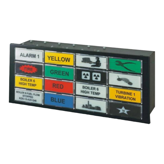
Front View of 16 Point Panel Mount Units Showing Display Layout and Numbering
Front View of Omni8C Panel Mount Units Showing Display Layout and Numbering
Front View of Omni8P Panel Mount Unit Showing Display Layout and Numbering
Figure 2-1 - Panel Mount Omni16C Front View Showing Window Numbers
Figure 2-2 - Panel Mount Omni8C Front View Showing Window Numbers
Figure 2-3 - Panel Mount Omni8P Front View Showing Window Numbers
Rear View of Omni16C 16 Point Units Showing Terminal Layout
Figure 2-4 - Omni16C Rear View
Rear View of Omni8C 8 Point Units Showing Terminal Layout
Figure 2-5 - Omni8C Rear View
Rear View of Omni8P 8 Point Units Showing Terminal Layout
Figure 2-6 - Omni8P Rear View
3 Mechanical Installation
Panel-Mount Mechanical Dimensions
Figure 3-1 - Panel Mount Omni16C and Omni8P Mechanical Dimensions
Figure 3-2 - Panel-Mount Omni8C Mechanical Dimensions
Wall-Mount Mechanical Dimensions
Introduction to Panel Mounting
Figure 3-3 - Wall-Mount Omni16C Standard Housing (Models C1478, C1479)
Figure 3-4 - Wall-Mount Omni8C/16C Compact Housing (Models C1180/1/2/3/4/5)
Panel Mounting Multiple Units in a Single Cut-Out
Mounting Procedure
Figure 3-5 - Jacking Bar Location Slots
Multiple Unit Cut-Out Size
Example Cut-Out Size Calculation
Figure 3-6 - Vertical Stacking Arrangement
Mounting Bar Kits
Mounting a Single Omni8/16C in a Panel Cut-Out
Intrinsically-Safe Annunciator Mechanical Mounting
Installation Requirements
IP65 Front Cover Mechanical Mounting
Figure 3-7 - Omni16C Ex IC Version in Protective Housing
Figure 3-8 - Omni16C IP65 Front Cover Mechanical Mounting
Figure 3-9 - Omni8 IP65 Front Cover Mechanical Mounting
Omni16 IP65 Front Cover Mounting Detail (C1433)
Omni8 IP65 Front Cover Mounting Detail (C1434)
Installing the Internal Pushbutton Station
Installing Back-Lit LED Boards
Removing Back-Lit LED Boards
Creating Window Legends for Back-Lit Display Windows
Overview
Creating the Legend Film
Inserting Legends and Colour Filters into Back-Lit Display Windows
Colour of Windows
Assembling Backlit Display Windows
Figure 3-10 - Backlit Window Order of Assembly
To Remove a Window
To Refit a Window
Creating Window Legends for Sidebar Display Windows
4 Electrical Installation
Introduction
Omni8C Block Diagram
Figure 4-1 - Omni8C Annunciator Block Diagram Showing Terminal Numbers
Omni8P Block Diagram
Figure 4-2 - Omni8P Annunciator Block Diagram Showing Terminal Numbers
Omni16C Block Diagram
Figure 4-3 - Omni16C Annunciator Block Diagram Showing Terminal Numbers
Intrinsically Safe (Ex IC) Omni16C-Ex Block Diagram
Figure 4-4 - Omni16C-Ex Annunciator Block Diagram Showing Terminal Numbers
Omni8C/8P/16C Terminal Schedule
Omni8C/8P/16C Serial Port Pinouts to PC or PLC
Figure 4-5 - RS232/485 Connector Pin-Out (Omni8C/16C/8P)
Power Requirements
Connecting the Power Supply
With no Internal Power Supply Installed (24Vdc Non Ex Versions)
With the Optional Internal Power Supply Installed (Non Ex Versions)
Omni16C Intrinsically Safe Version (Ex IC)
24Vdc Power Externally Available (Non Ex Versions Only)
Connecting the Alarm Inputs
With Potential Free Contacts
Figure 4-6 - Input Connection Diagram Using Individually Wired Potential Free Contacts
With Optional Isolated Input Card
Figure 4-7 - Input Connection Diagram Using Common Return Wire
Figure 4-8 - Input Connection Diagram Using Isolated Input Cards (External Supply)
With Optional High Voltage Input Cards
Ribbon Header Input Cards
Connecting the Common Service Relay Contacts
Figure 4-9 - Input Connection Diagram Using High Voltage Input Cards
Switch Set Mode
Connecting Control Pushbuttons
Controlling a Single Omni8/16C with Internal Pushbuttons
Controlling a Single Omni8/16C with External Pushbuttons
Figure 4-10 - External Pushbuttons Controlling a Single Omni8/16C
Controlling Multiple Omni8/16C's with External Pushbuttons
Controlling Multiple Omni8/16C's with an Integral Pushbutton Station
Figure 4-11 - External Pushbuttons Controlling Multiple Omni8/16C's
Figure 4-12 - Internal Pushbutton Station Controlling Multiple Omni8/16C Units
Controlling Multiple Omni8C/16C's with an Omni8P Alarm Annunciator
Connecting the C1415 Remote Pushbutton Station
Figure 4-13 - Omn8P Annunciator Controlling Multiple Omni8C/16C Units
Figure 4-14 - Connecting C1415 Remote Pushbutton Station to Omni8/16C Units
Connecting the Omni8P Internal Audible Device
Connecting the Omni8P Internal Audible Device to Other Omni8/16C's
Figure 4-15 - Connecting the Internal Omni8P Audible Device
Figure 4-16 - Connecting Omni8P Audible to Omni16C's
Connecting the C1169 Lamp Driver Board Outputs
Connecting the Inhibit Input
Connecting the Optional Input Repeat Relay Contacts (Model C1425)
Figure 4-17 - Connecting the Optional C1169 Lamp Driver Board
Connecting the Optional Ribbon Header Outputs (Model C1426)
Figure 4-18 - Ribbon Header Pin Layout
Figure 4-19 - Open Collector Transistor Output Arrangement
Synchronising Flashing between Multiple Omni8/16C's
Expanding First-Out Groups between Multiple Omni8/16C's
Electrical Installation Requirements for Intrinsically Safe Annunciators
5 Configuring the Omni8/16C for Operation
Introduction
Modes of Operation
Selecting the Input Sense
Selecting the Alarm/Display Logic Sequences
Selecting the Group Alarm Relay (RL3) Output Function
Selecting the Inhibit Input Contact Sense
Selecting the Lamp Status
Selecting Time Delays
Figure 5-1 - Setting Time Delays on SW2
Explanation of Timer Operation in a Timer Sequence
Omni8/16C Fast and Slow Timers
Selecting Serial Port Settings
Default Settings
Modbus Address and Mode Settings
Figure 5-3 - Serial Port Settings on SW2
Changing the Operation of the Repeat Outputs
6 Operation
Power up
Normal Operation
Test Functions
Overview of the Test Functions
Pressing the Test Button
Fault Indication on Circuit Test
Manually Invoking the Circuit Test Function
The "Marching Sequence" Circuit Test Display
Use of the Inhibit Input
7 Functional Safety Manual
Function Specification
Hardware Configuration
Installation Requirements
Functional Safety Parameters
Diagnostics
Proof Test
Prevention of Systematic Failures
8 Specifications
9 Alarm Sequence Diagrams
10 Modbus Register Layout
Advertisement
Quick Links
Download this manual
Omni8C/16C/Omni8P Series
Alarm Annunciators & Serial Displays
User Manual
Revision 24
Table of
Contents
Previous
Page
Next
Page
1
2
3
4
5
Advertisement
Table of Contents
Need help?
Do you have a question about the Omni8C Series and is the answer not in the manual?
Ask a question
Questions and answers
Related Manuals for Omniflex Omni8C Series
Monitor Omniflex Omni16C Series User Manual
Alarm annunciators & serial displays (105 pages)
This manual is also suitable for:
Omni16c series
Omni8p series
C1496a
C1497a/8a
C1499a
C1486a
...
Show all
C1487a/8a
C1489a
C1180
C1181
C1478
C1479
C1182
C1184
C1185
C1490b
C1491b
C1492b
C1493b
C1494b
C1495b
C1427a
C1428a
C1429a
C1480b
C1481b
C1482b
C1483b
C1484b
C1485b
C1480b-ex
C1480
C1481
C1482
C1483
C1484
C1485
C1490
C1491
C1492
C1493
C1494
C1495
Table of Contents
Print
Rename the bookmark
Delete bookmark?
Delete from my manuals?
Login
Sign In
OR
Sign in with Facebook
Sign in with Google
Upload manual
Upload from disk
Upload from URL


Need help?
Do you have a question about the Omni8C Series and is the answer not in the manual?
Questions and answers