
Related Manuals for BYD CBH-40A


Summarization of Contents
Information on this Document
Validity
Document validity for CBH-40A.
Target Group
Specifies qualified persons and required skills for installation and operation.
Symbols
Explains hazard and notice symbols used in the manual.
Safety
Intended Use
Defines the product's intended purpose and manufacturer's liability.
Instructions and Warnings
Emphasizes reading and understanding safety instructions for preventing serious consequences.
Position and Securing
Provides guidance on safe placement and mounting of the Combiner Box.
Safety Precautions
Outlines essential safety precautions for personal injury, property damage, and product longevity.
Product Description
Circuit Diagram
Illustrates the electrical connections and components of the CBH-40A Combiner Box.
Type Label
Details the information found on the device's type label for identification and support.
Symbols on the Type Label
Explains the meaning of symbols present on the product's type label.
Assembly
Wall Mounting
Covers selecting the mounting location and the process of attaching the box.
Selecting the Mounting Location
Guidelines for choosing the optimal and safe placement for the Combiner Box.
Mounting the Combiner Box
Instructions and precautions for the physical installation of the Combiner Box.
Electrical Connection
Connection Instructions
Steps and guidelines for properly connecting the device electrically.
Preliminary Checks
Crucial pre-connection checks to ensure safety and proper installation of the Combiner Box.
Safety during Electrical Connection
Critical safety measures to follow during the electrical connection process.
Inserting the Cables into the Switch Cabinet
Instructions for routing cables into the main unit's cabinet.
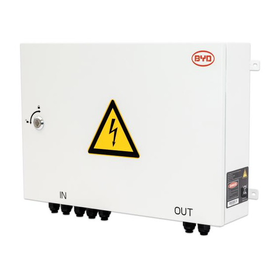
Bottom view of Combiner Box with cable glands
Illustrates the bottom of the box, showing cable glands and their corresponding ports.
Overview of the Connection Area
Provides a detailed view and explanation of the internal connection points.
Leading the Cables through the Cable Glands with sealing Gasket
Step-by-step guide for correctly routing cables through the gland seals.
Connecting the DC Cables
Detailed procedure for connecting the DC power cables to the device.
Connecting the Grounding Cable
Procedure for securely connecting the grounding cable to the designated post.
Maintenance
Periodic Maintenance
Recommended regular inspections for the panel to ensure functionality and safety.
Extraordinary Maintenance
Guidelines for replacing damaged components and handling repairs.
Decommissioning
Disassembling the Combiner Box
Safety rules and procedures for safely disconnecting and dismantling the Combiner Box.
Disposing of the Combiner Box
Instructions for proper disposal of the Combiner Box according to electronic waste regulations.
Need help?
Do you have a question about the CBH-40A and is the answer not in the manual?
Questions and answers