Table of Contents
Advertisement
3/23/2021
Home
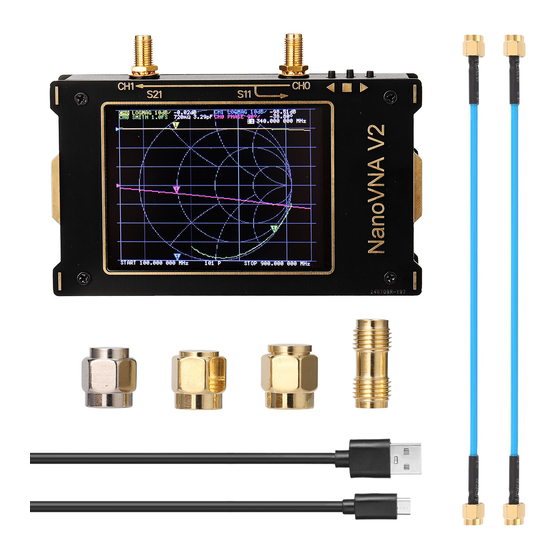
NanoVNA V2
Hardware versions /
Firmware downloads
Software downloads
User manual
Forum / Users group
Other docs
FAQ
For distributors
Contact Us
https://nanorfe.com/nanovna-v2-user-manual.html
< Back to NanoVNA V2
NanoVNA V2 / S-A-A-2 User Manual
UG1101 2020/09
User Manual | NanoVNA V2
1/37
Advertisement
Table of Contents

Related Manuals for NANO S-A-A-2

Summarization of Contents
Introduction to NanoVNA V2
Manual Content Credits
Acknowledges derivation of manual content from an external source.
Comparison with Original NanoVNA
Compares NanoVNA V2 hardware and firmware to the original NanoVNA.
User Interface Navigation and Controls
Main Screen Display Elements
Details the components and information displayed on the NanoVNA V2 main screen.
Accessing the Menu Screen
Explains how to access the main menu from the touch screen or button.
Keypad Input Interface
Describes the numeric keys, back key, unit key, and input field.
Device Settings Configuration
Covers general settings like calibration info, grid, and trace colors.
Firmware Update Mode Activation
Instructions on how to enter DFU mode for device firmware updates.
Touch Panel Calibration Procedure
Procedure for calibrating and testing the LCD touch panel accuracy.
Performing Measurements
Basic Measurement Sequence
Outlines the basic sequence: set frequency, calibrate, connect DUT, measure.
Measurement Frequency Range Settings
Setting Start and Stop Frequencies
Configures the sweep range using start and stop frequency values.
Setting Center Frequency and Span
Defines the sweep range by specifying a center frequency and span.
Zero Span Operation
Enables continuous transmission at a single frequency without sweeping.
Temporarily Pausing Sweep
Allows pausing the measurement sweep when the 'PAUSE SWEEP' option is active.
Device Calibration
Calibration Procedure and Standards
Details the process of connecting standards (Open, Short, Load, Thru) for calibration.
Trace Display Management
Explains how to display, activate, and manage up to four traces.
Trace Format Options
Describes available formats like LogMag, Phase, Smith Chart, SWR.
Trace Channel Selection
How to switch between CH0 (S11) and CH1 (S21) for active traces.
Using Markers
Setting Frequencies Using Markers
Utilizes markers to set start, stop, center frequencies, and span.
Time Domain Analysis
Time Domain Bandpass Mode
Simulates DUT response to an impulse signal in bandpass mode.
Time Domain Low Pass Mode for TDR
Simulates TDR in low-pass mode with specific frequency requirements.
Time Domain Low Pass Step Response
Provides example measurements of step response for various conditions.
Time Domain Windowing Options
Explains MINIMUM, NORMAL, and MAXIMUM windowing for data smoothing.
Setting Velocity Factor for Distance
Configures the velocity factor for converting time domain data to distance.
NanoVNA-QT PC Software
NanoVNA-QT User Interface
Details the software's graphical user interface elements.
Connecting NanoVNA to PC via USB
Step-by-step guide for establishing a USB connection between device and PC.
Software Sweep Parameter Configuration
Configuration of sweep range and parameters using the PC software.
Software Calibration Procedure
Instructions for performing calibration using the NanoVNA-QT application.
Software Calibration Kit Configuration
Setting up custom calibration kit parameters within the software.
Firmware Update with NanoVNA-QT
Procedure for updating the NanoVNA V2 firmware using the PC software.
Appendix I: Hardware Architecture
System Block Diagram
High-level overview of the NanoVNA V2 system components and connections.
Signal Generators and Coupler
Details on RF synthesizers, LO signals, and the directional coupler design.
Receiver Components and Function
Description of the receiver circuitry, mixer, and digital signal processing.
Appendix II: USB Data Interface
USB Communication Protocol
Explains the USB CDC virtual serial port communication protocol.
Host to Device Command List
Lists supported commands for PC to device communication and their formats.
Register Descriptions (Normal Operation)
Details accessible device registers and their functions during normal use.
FIFO Data Format Specification
Specifies the structure and content of data read from the FIFO buffer.
Register Descriptions (DFU Mode)
Lists accessible device registers and their functions in DFU mode.
Writing Firmware to Flash Memory
Procedure for writing new firmware images to the device's flash memory.
Need help?
Do you have a question about the S-A-A-2 and is the answer not in the manual?
Questions and answers