Table of Contents
Advertisement
3/23/2021
Home
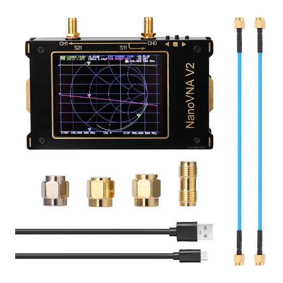
NanoVNA V2
Hardware versions /
Firmware downloads
Software downloads
User manual
Forum / Users group
Other docs
FAQ
For distributors
Contact Us
https://nanorfe.com/nanovna-v2-user-manual.html
< Back to NanoVNA V2
NanoVNA V2 / S-A-A-2 User Manual
UG1101 2020/09
User Manual | NanoVNA V2
1/37
Advertisement
Table of Contents

Need help?
Do you have a question about the NanoVNA V2 and is the answer not in the manual?
Questions and answers
Nano vna v2 после установки нужного диапазона и калибровки не сохраняет в памяти выбранные параметры.
The NanoVNA V2 does not automatically save selected parameters after setting the desired range and calibration because calibration is invalidated whenever the frequency range is changed. To preserve settings, users must manually save calibration data using CAL → SAVE → SAVE n. Without saving, settings are lost when the range is changed or the device is restarted.
This answer is automatically generated