Table of Contents
Advertisement
Quick Links
A MIDDLEBY COMPANY
OWNER'S
OPERATING
& INSTALLATION
MANUAL
X70G/X55G-Series Gas Ovens
Models X70G & X55G
© 2021 Middleby Marshall Inc.
is a registered trademark of Middleby Marshall, Inc. All rights reserved.
1
X70G/X55G-Series Gas Ovens: English
Combinations:
• Single Oven
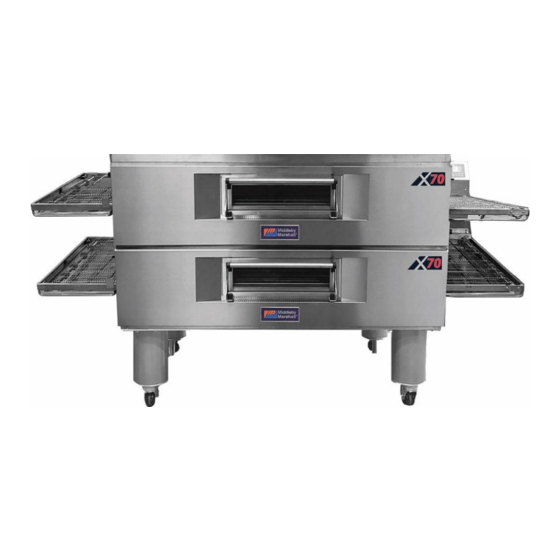
• Double Oven (Two-Stack)
• Triple Oven (Three-Stack)
P/N 77538 rev B
Advertisement
Table of Contents

Related Manuals for Middleby Marshall X55G Series


Summary of Contents for Middleby Marshall X55G Series
- Page 1 MANUAL Combinations: X70G/X55G-Series Gas Ovens • Single Oven Models X70G & X55G • Double Oven (Two-Stack) • Triple Oven (Three-Stack) © 2021 Middleby Marshall Inc. is a registered trademark of Middleby Marshall, Inc. All rights reserved. P/N 77538 rev B...
- Page 2 Gas Conversion Kit. For your safety, do not store or use gasoline or other Middleby Marshall suggests a service contract with a flammable vapors and liquids in the vicinity of this or Middleby Authorized Service Agent (ASA).
- Page 3 Seller shall not be liable for any prospective or lost profits of Buyer. for any prospective or lost profits of the buyer. This warranty is effective on Middleby Marshall equipment sold The foregoing shall be Seller’s sole and exclusive obligation and on, or after January 1st, 2007.
-
Page 4: Table Of Contents
Table of Contents SECTION 1 DESCRIPTION ..........5 IV. ELECTRICAL CONNECTION ........ 24 MODEL IDENTIFICATION ........5 V. GAS CONNECTION ..........24 II. X70G/X55G SERIES SPECIFICATIONS....6 A. Gas Conversion ..........25 III. COMPONENT FUNCTION ........7 B. X70G/X55G Propane Conversion Kit 77601 ..25 A. -
Page 5: Section 1 Description
Oven Features X70G Single Oven Middleby Marshall continuous batch conveyor ovens bake both faster and at a lower temperature than other ovens. Patented vertical columns of hot air move heat aerodynamically instead of using high temperatures. -
Page 6: X70G/X55G Series Specifications
SECTION 1 DESCRIPTION II. X70G/X55G SERIES SPECIFICATIONS RECOMMENDED MINIMUM CLEARANCES Rear of Oven to Wall Control end of Conveyor to Wall Non-control end of Conveyor to Wall Domestic and std. export 6" 6" 6" 152mm 152mm 152mm X70G/X55G SERIES OVEN SPECIFICATIONS Dimensions Single Oven Double Oven... -
Page 7: Component Function
SECTION 1 DESCRIPTION X70G/X55G Series Oven Component Locations III. COMPONENT FUNCTION G. High Limit Reset Button On rear of control box. A. On/Off Switch & Control Panel (User Interface) H. End Plugs On/Off switch allows the operator to completely power Allows access to the oven’s interior baking chamber. - Page 8 SECTION 1 DESCRIPTION NOTES:...
-
Page 9: Section 2 Installation
SECTION 2 INSTALLATION SECTION 2 INSTALLATION WARNING NOTICE For additional installation information, contact your After conversions, readjustments, service work on the oven: local Authorized Service Agent. • Perform a gas leak test. NOTICE • Test for correct air supply, particularly to the There must be adequate clearance between the burner blower. -
Page 10: Unloading And Rough-In
I. UNLOADING AND ROUGH-IN of crates. If apparent damage is found, make arrangements to file a claim against the carrier. Your Middleby Marshall X70G/PX55G-Series Oven is Surface Interstate Commerce Regulations (U.S.A.) shipped partially assembled. It will arrive in a carton on require that the claim must be initiated by the a crate. - Page 11 SECTION 2 INSTALLATION PARTS LIST FOR SINGLE and DOUBLE X70G OVEN BASE/TOP KIT with 15" LEGS P/N: 76771 ITEM NO. PART NO. DESCRIPTION 76772 BASE ASSEMBLY (X70 Series) 77470 COVER ASSEMBLY/CORNER BRACE with SCREWS 61828 15" LEG WELDMENT 74319 6" CASTER with BRAKE & 4" WHEEL 22450‐0028 6"...
- Page 12 SECTION 2 INSTALLATION PARTS LIST FOR SINGLE and DOUBLE X55G OVEN BASE/TOP KIT with 15" LEGS P/N: 77086 ITEM NO. PART NO. DESCRIPTION 22450-0228 RESTRAINING DEVICE 77088 BASE ASSEMBLY (X55 Series) 77492 COVER ASSEMBLY/CORNER BRACE 61828 15" LEG WELDMENT 74319 CASTER STUD with BRAKE &...
- Page 13 SECTION 2 INSTALLATION PARTS LIST FOR SINGLE and DOUBLE X70G OVEN BASE/TOP KIT with 10" LEGS P/N: 77609 ITEM NO. PART NO. DESCRIPTION 76772 BASE ASSEMBLY (X70 Series) 77470 COVER ASSEMBLY/CORNER BRACE 70049 10" LEG WELDMENT PS360G 74319 CASTER with BRAKE & 4" WHEEL 22450‐0028 6"...
- Page 14 SECTION 2 INSTALLATION PARTS LIST FOR SINGLE and DOUBLE X55G OVEN BASE/TOP KIT with 10" LEGS P/N: 77613 ITEM NO. PART NO. DESCRIPTION 22450-0228 RETRAINING DEVICE 77088 BASE ASSEMBLY (X55 Series) 77492 COVER ASSEMBLY TOP/CORNER BRACE 70049 10" LEG WELDMENT PS360G 74319 CASTER with BRAKE &...
- Page 15 SECTION 2 INSTALLATION PARTS LIST FOR TRIPLE X70G OVEN BASE/TOP KIT P/N: 77610 ITEM NO. PART NO. DESCRIPTION 76772 BASE ASSEMBLY (X70 Series) 77470 COVER TOP ASSEMBLY/CORNER BRACE 70060 LEVELING CASTER (1650 LBS) 21416‐0003 WASHER, FLAT 1/2 SS 2001045 SCREWS CAP HX HD 1/2-13X1 ZP 21426‐0004 WASHER, LOCK 1/2 SS 31239...
- Page 16 SECTION 2 INSTALLATION PARTS LIST FOR TRIPLE X55G OVEN BASE/TOP KIT P/N: 77614 ITEM NO. PART NO. DESCRIPTION 22450-0228 RESTRAINING DEVICE 77088 BASE ASSEMBLY (X55 Series) 77492 COVER TOP ASSEMBLY/CORNER BRACE 70060 LEVELING CASTER (1650 LBS) A27721 WASHER, LOCK 3/8 220373 SCREWS CAP HX HD 3/8-16X1 18-8 21416‐0001...
- Page 17 SECTION 2 INSTALLATION UTILITY ROUGH-IN FOR X70G/X55G-SERIES OVENS Utility Connection Locations for Gas Ovens Check the oven serial plate before making any electric WARNING supply connections. Electric supply connections must Do not use conduit or gas line for ground agree with data on the oven serial plate. The location connection.
- Page 18 SECTION 2 INSTALLATION Gas Piping Requirements ITEM NO. DESCRIPTION Nat Gas GAS SUPPLY PIPE 2" 2" 2" x 1-1/4" 2" x 1-1/4" DRIP LEG 2" 2" 2" 2" NIPPLE 1-1/4" 1-1/4" FULL-FLOW SHUTOFF VALVE 1-1/4" 1-1/4" NIPPLE 1-1/4" 1-1/4" 1-1/4" REGULATOR DYNAMIC READING 8"-12"...
-
Page 19: Ventilation Guidelines
SECTION 2 INSTALLATION II. VENTILATION GUIDELINES air that was exhausted. A negative pressure in the kitchen can cause heat related problems to the oven NOTICE components as if there were no ventilation at all. The best method of supplying return air is through the Proper ventilation of the oven is the responsibility of heating, ventilation and air conditioning (HVAC) the owner. -
Page 20: Assembly
SECTION 2 INSTALLATION III. ASSEMBLY A. Base Pad and Leg Assembly 1. Install the four leg extensions onto the base pad using the 1/2"-13 x 1-1/4" hex screws, 1/2" flat washers and 1/2" lock washers supplied in the base pad kit. See Figure 15. Check that the orientation of the adjustable 6"... -
Page 21: Stacking
See Figure 19. DO NOT stack X70G/X55G ovens underneath or between PS770/PS570 oven units. Contact your Middleby Marshall Authorized Service Agent for complete stacking instructions. 1. Stack an oven cavity on top of the lower oven. -
Page 22: Conveyor Installation
SECTION 2 INSTALLATION D. Conveyor Installation 1. Unfold the conveyor as shown in Figure 20. Then begin to slide the conveyor into the end of the oven. The conveyor can only be installed from the side of the oven where the drive motors are located. -
Page 23: Final Assembly
SECTION 2 INSTALLATION Remove the master links using long-nose F. Conveyor Belt Reversal pliers. Then, roll up the belt along the length Conveyor belt reversal consists of two steps: of the conveyor frame. Add or remove belt links as necessary to 1. -
Page 24: Electrical Connection
INSTALLATION The terms of the oven’s warranty require all start-ups, conversions and service work to be performed by a 4. Press again to leave the SYSTEM Middleby Marshall Authorized Service Agent. CONFIGURATION menu. V. GAS CONNECTION SWITCHING PHOTO SENSOR CAUTION... -
Page 25: Gas Conversion
SECTION 2 INSTALLATION location shown in Figure 28, which also shows the gas train and burner assembly. NOTE: The installation must conform with local codes or in the absence of local codes, with the National Fuel Gas Code, ANSI Z223.1-latest edition. Certain safety code requirements exist for the installation of gas ovens;... - Page 26 SECTION 2 INSTALLATION Gas Train and Burner Assembly...
-
Page 27: Section 3 Operation
SECTION 3 OPERATION SECTION 3 OPERATION I. DESCRIPTION OF CONTROLS – USER INTERFACE “TEMPERATURE” key: The X70/X55 oven control performs a variety of Quick press displays actual temperature. − functions, including: Pressing and holding until display flashes − − Temperature control allows a change to set temperature. -
Page 28: Display Features
SECTION 3 OPERATION B. Display Features II. NORMAL OPERATION B. Adjusting the Temperature To adjust the set temperature, press and hold the A. Daily Start-up Procedure To start the oven, first turn the ON/OFF rotary power button until the set temperature display flashes. switch to the ON position, wait for the screen to illuminate and boot up (30-second count-down). -
Page 29: Adjusting The Belt Time
SECTION 3 OPERATION previously used set temperature will appear when the oven is turned ON again. C. Adjusting the Belt Time To adjust the belt time, press and hold the button until the belt time display flashes. Press the button until the desired belt time is displayed. -
Page 30: System Setup
SECTION 3 OPERATION C. System Setup D. Energy Management Information Enter SYSTEM SETUP menu (Can only be done in OFF mode). Four control system values can be changed that relate to the user interface for the daily oven operator: 1. Actual temperature display always on or off The X70/X55 oven reduces energy usage in two ways 2. -
Page 31: Section 4 Maintenance
ONLY be replaced by a perform the following procedure: Middleby Marshall Authorized Service Agent. It is also 1. Switch off the oven and allow it to cool. Do NOT strongly recommended that the 3-Month Maintenance service the oven while it is warm. - Page 32 SECTION 4 MAINTENANCE 3. Loosen chain guard. 6. Slide the conveyor out of the oven, folding it as it is removed. 4. Slide the chain guard up. 7. Remove the end plugs from the oven. 5. Lift the drive end of the conveyor slightly (1) and push it forward into the oven (2).
- Page 33 SECTION 4 MAINTENANCE 9. AS EACH BLANK PLATE OR AIR FINGER IS REMOVED, WRITE A “LOCATION CODE” ON IT WITH A MARKER to make sure it can be reinstalled correctly. Example of markings: (Top Row) (Bottom Row) 10. Remove, empty, and clean the drip pans. 11.
-
Page 34: Maintenance - Every 3 Months
SECTION 4 MAINTENANCE Drive chains End plugs Conveyor assembly Remove the master links from each conveyor belt. Then, roll the belts up along the length of the conveyor to remove them from the frame. Remove the two conveyor adjustment screws from the idler end of the conveyor frame, as shown in Figure 30. -
Page 35: Maintenance - Every 6 Months
SECTION 4 MAINTENANCE removed, lift the end of the shaft at the front of the oven, and pull the entire assembly free of the conveyor frame. The brackets will be removed along with the drive shaft assembly. Before reassembling the shafts into the conveyor frame, check that they are oriented properly. -
Page 36: Key Spare Parts
SECTION 4 MAINTENANCE V. KEY SPARE PARTS Replacement parts can be purchased from your Middleby Marshall Authorized Parts Distributor (See Figure 31). X70G/X55G-SERIES GAS OVEN KEY SPARE PARTS (Figure 31) ITEM PART NO. ENGLISH DESCRIPTION QUANTITY 74106 Motor, Conveyor Drive... - Page 37 SECTION 4 MAINTENANCE...
- Page 38 SECTION 4 MAINTENANCE NOTES...
-
Page 39: Section 5 Troubleshooting
SECTION 5 TROUBLESHOOTING SECTION 5 TROUBLESHOOTING I. TROUBESHOOTING GUIDE SYMPTOM POSSIBLE CAUSES SOLUTIONS Nothing displayed on controller 1. Main Switch is OFF. 1. Turn on main power switch. 2. High Limit has tripped. 2. Turn power OFF to reset. 3. Power not connected. 3. -
Page 40: Alerts, Errors & Remedies
Turn oven off and back on again to 3. Burner has stopped running. clear the notification and relight. NOTE: If the remedial measures above do not successfully resolve the issue, or the issue is not listed above, contact the Middleby Marshall Customer Care Center at +1-847-429-7852. -
Page 41: Section 6 Electrical Schematics
SECTION 6 ELECTRICAL SCHEMATICS SECTION 6 ELECTRICAL SCHEMATICS Wiring Diagram, G208-240 AC 50/60 Hz X70 • 76914 REV C... - Page 42 SECTION 6 ELECTRICAL SCHEMATICS...
- Page 43 SECTION 6 ELECTRICAL SCHEMATICS Wiring Diagram, G208-240 AC 50/60 Hz X55 • 77605 REV B...
- Page 44 SECTION 6 ELECTRICAL SCHEMATICS...
- Page 45 SECTION 6 ELECTRICAL SCHEMATICS NOTES...
- Page 46 NOTICE During the warranty period, ALL parts replacement and servicing should be performed by your Middleby Marshall Authorized Service Agent. Service that is performed by parties other than your Middleby Marshall Authorized Service Agent may void your warranty.
Need help?
Do you have a question about the X55G Series and is the answer not in the manual?
Questions and answers