Table of Contents

Related Manuals for Evnex X Series


Summary of Contents for Evnex X Series
- Page 1 Installer & Operator Manual Intelligent EV Charging Station E7, X7 & X22 Series V210211 E & X Series As well as standard installation tools, the following is required: • T20 TORX SECURITY BIT • NO.2 SQUARE DRIVE BIT • 7MM MASONRY BIT (FOR SOLID WALLS)
- Page 2 Phone: +64 3 925 9879 Email: support@evnex.com Web: www.evnex.com Address: 239 Brougham St Sydenham Christchurch 8023 New Zealand © Evnex Limited All rights reserved. Evnex E & X Series Installation Manual | V210 211...
-
Page 3: Table Of Contents
Wiring connection ..................18 Single phase wiring example ..............19 Three phase wiring example ..............20 Upstream protection ................21 Accessory terminal block ..............23 Earthing the unit ..................23 Evnex E & X Series Installation Manual | V210 211... - Page 4 Installing the front cover ............... 25 Operation ....................26 Status display ..................26 Initialisation ................... 26 Charging process .................. 27 LED modes / fault conditions..............28 Technical information ................29 Troubleshooting ..................33 Evnex E & X Series Installation Manual | V210 211...
-
Page 5: Introduction
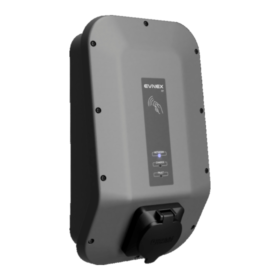
Introduction Product description The Evnex E & X Series charging stations are a cost effective connected charging solution, available in both single phase 7.4kW, and three phase 22kW configurations. When connected to a compatible OCPP (Open Charge Point Protocol) server, the Evnex E & X Series charging stations become an excellent choice for smart-grid managed charging or public charging, where energy metering or access control is required. -
Page 6: About This Document
About this document The following document describes the functionality and installation procedures for the Evnex E & X Series of electric vehicle charging stations. Scope of this document This document only refers to the following E & X Series charging stations, please refer to the correct documentation if this does not apply. -
Page 7: Safety Information
3 and IEC 61000-6-2, however the installer is responsible for ensuring that all local regulations and standards are complied with. • This product is to be serviced only by Evnex approved technicians using only Evnex supplied parts • There are no user serviceable parts inside the charging station. -
Page 8: Risk Of Electric Shock
Do not use extension cords or any kind of adapter with this product • This product should not be used by children • Avoid installing this product in locations that are prone to flooding Evnex E & X Series Installation Manual | V210 211... -
Page 9: Disclaimer
Disclaimer Evnex Limited shall not be liable in any way for damage or injury that occurs when using the product, and all warranties will be void where: • The installation instructions have not been followed correctly • The product has been installed by an unqualified person •... -
Page 10: Installation
Where possible, protect the charging station from direct sunlight to prevent charging speed reduction or charging interruption due to overheating • Do not cover unit or install in an area with poor airflow, such as a cupboard Evnex E & X Series Installation Manual | V210 211... - Page 11 Product to be installed with adequate clearance to prevent operator injury while using product. This includes inserting and removing charging connector, wrapping and unwrapping cable and operating the RFID card reader Evnex E & X Series Installation Manual | V210 211...
-
Page 12: Mounting Notes
5 locations specified. It is the installers responsibility to ensure proper sealing of any drilled holes, including installation of provided sealing plugs. See arrows showing the 5 drilling locations. Evnex E & X Series Installation Manual | V210 211... -
Page 13: Fasteners
Fasteners Locate the packet labelled INSTALLATION MANUAL & FASTENERS containing the following: *No.2 square bit required **Torx T20 security bit required Evnex E & X Series Installation Manual | V210 211... -
Page 14: Opening The Unit
The cover has a tether to decrease risk of wire strain. This tether can be looped into the recess in the top right corner of the enclosure to keep the cover out of the way during installation. Evnex E & X Series Installation Manual | V210 211... -
Page 15: Mounting The Unit
The location of the optional rear entry hole (M25 or M32) is also provided, along with the optional M12 hole location. M12 and M32 holes need to be drilled by the installer if required. Evnex E & X Series Installation Manual | V210 211... -
Page 16: Timber Framed Wall Mounting Example
Timber framed wall mounting example Evnex E & X Series Installation Manual | V210 211... -
Page 17: Solid Wall Mounting Example
Recommended hole depth is 40mm with a 7mm masonry bit. For all types of installation ensure that the washers are installed on the screws and that the sealing plugs are installed after the screws are firmly tightened. Evnex E & X Series Installation Manual | V210 211... -
Page 18: Wiring Connection
The E & X Series of charging stations are not designed to charge vehicles that require ventilation systems during charging. Charging station is not to be powered on while the front cover is open Evnex E & X Series Installation Manual | V210 211... -
Page 19: Single Phase Wiring Example
Single phase wiring example Evnex E & X Series Installation Manual | V210 211... -
Page 20: Three Phase Wiring Example
Excess wire may cause interference and prevent the unit from being properly closed Evnex E & X Series Installation Manual | V210 211... -
Page 21: Upstream Protection
• The maximum rated short-circuit capacity (I ) is 6000 A. • The circuit breaker must comply with one of the following standards: IEC 60898-1, IEC 60947-2, or IEC 61009-1. Evnex E & X Series Installation Manual | V210 211... - Page 22 DC leakage currents. In the event of detecting a DC leakage current, the charge point will immediately stop the charging session and transition into a fault state, requiring a reboot to clear the state. Evnex E & X Series Installation Manual | V210 211...
-
Page 23: Accessory Terminal Block
Depending on the capacity of your upstream supply, the maximum charging current can be set lower than 32A via the DIP switches during installation. The DIP switches set the maximum allowable current that the charging station will draw. Evnex E & X Series Installation Manual | V210 211... -
Page 24: Closing The Unit
Install the cover, tightening the ten cover fasteners to 2.5 N-m using a T20 Torx security bit. Evnex E & X Series Installation Manual | V210 211... -
Page 25: Installing The Front Cover
Installing the front cover Evnex E & X Series Installation Manual | V210 211... -
Page 26: Operation
OCPP server. When the NETWORK light begins to fade in and out slowly, the charging station has successfully established a connection with the server. Evnex E & X Series Installation Manual | V210 211... -
Page 27: Charging Process
During the charge, the CHARGE light on the unit will glow green. After charging, tethered cable should be stored safely by wrapping it around unit. Non-tethered cables may be removed or wrapped around unit. Evnex E & X Series Installation Manual | V210 211... -
Page 28: Led Modes / Fault Conditions
RFID tag detected 5 flashes RFID tag not recognised Do not use the charging station if the plug and lead or socket are cracked, frayed, or damaged in any way Evnex E & X Series Installation Manual | V210 211... -
Page 29: Technical Information
Acceptable operating range………………………………..……………..…...400±10% VAC (3P+N) Frequency………………………………………………………….………….………………..………………..50/60 Hz Rated Current…………………………………………………………..………….…….Adjustable (max 32A) *Note that actual current draw may be less, as the vehicle may not request the full amount of current, depending on conditions. Evnex E & X Series Installation Manual | V210 211... - Page 30 Energy metering……………………………………………………………..………………..Yes, MID certified WiFi……………………………………………………………………………………………………………..802.11b/g/n Ethernet…………………………………………………………………………………………………………………..…Yes Protection & safety features Over voltage cut-off………………………………….…………………………………………………...……..264V Under voltage cut-off…….……………………………………………………………………………………...190V Over current cut-off……………………….………...1.25x max current setting or cable limit Over temperature cut-off………………………….…………………………………………….……………70 °C Ground fault detection…………...…………………………………………………………………………….…Yes Evnex E & X Series Installation Manual | V210 211...
- Page 31 EN 300 328 V2.1.1 • Low Voltage Directive 2014/35/EU IEC 61851-1:2017 • EMC Directive 2014/30/EU IEC 61000-6-3:2011 IEC 61000-6-2:2005 • RoHS Directive 2011/64/EU IEC 63000:2016 • WEEE Directive 2012/19/EU EN 50419:2006 Evnex E & X Series Installation Manual | V210 211...
- Page 32 Locations with restricted and non- restricted access Protection against electric shock IEC61851-1 Class I equipment Mounting method Stationary equipment (Surface mounted on walls, poles or equivalent positions) EVSE charging mode EC61851-1 Mode 3 Evnex E & X Series Installation Manual | V210 211...
-
Page 33: Troubleshooting
The unit responds with 5 red flashes Ensure that the RFID card is when swiping an RFID card recognised and correctly loaded in the back office software Evnex E & X Series Installation Manual | V210 211... - Page 34 If any issues persist, please contact customer support. SDoC available on request. Evnex E & X Series Installation Manual | V210 211...
Need help?
Do you have a question about the X Series and is the answer not in the manual?
Questions and answers