
Related Manuals for rotork YT-870M


Summarization of Contents
Introduction
General Information for the users
Provides essential information for users regarding product usage and manual handling.
Manufacturer Warranty
Details the terms and conditions of the manufacturer's warranty, including coverage and exclusions.
Explosion Proof Warning
Highlights critical safety warnings and precautions related to explosion-proof environments and usage.
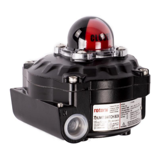
Product Description
General
Provides a brief overview of the YT-870/875 series limit switch box function.
Main Features and Functions
Outlines the key features and operational capabilities of the limit switch box.
Label Description
Explains the meaning and purpose of various labels and markings on the product.
Product Code
Details the product coding system for specifying model variations and options.
Product Specification
Provides detailed technical specifications for different models of the limit switch box.
Limit Switch Specification
Details electrical and mechanical specifications for the limit switches.
Specification of SPTM(Smart Position Transmitter) option
Details the technical specifications for the optional Smart Position Transmitter (SPTM).
Certifications
Lists the various certifications and compliance standards applicable to the product.
Parts and Assembly
Illustrates the components of the limit switch box and provides assembly information.
Product Dimension
Shows the physical dimensions and measurement details of the limit switch box.
Bracket Dimension
Provides the dimensions for the various mounting bracket types available for the product.
Installation
Safety
Outlines essential safety instructions and precautions to be followed during installation.
Installation
Describes the step-by-step process for installing the limit switch box onto an actuator.
Connections - Power
Safety
Emphasizes crucial safety guidelines to adhere to when making power connections.
Mechanical Type (2 x SPDT)
Illustrates the wiring diagram and connection points for the 2 x SPDT mechanical switch type.
Inductive proximity sensor (x 2, Autonics, PSN17-5DNU, NPN type)
Shows the wiring diagram for connecting 2 Autonics NPN type inductive proximity sensors.
Inductive proximity sensor (x 2, P&F, NJ2-V3-N, NC type)
Details the wiring diagram for connecting 2 P&F NC type inductive proximity sensors.
Mechanical Type (2 x DPDT)
Provides the wiring diagram for the 2 x DPDT mechanical switch type.
Internal SPTM(Smart Position Transmitter)
Illustrates the internal connections and configuration for the Smart Position Transmitter (SPTM) option.
Adjustments
Upper Switch Adjustment
Explains how to adjust the upper limit switch cam for proper positioning.
Lower Switch Adjustment
Details the procedure for adjusting the lower limit switch cam for correct operation.
Need help?
Do you have a question about the YT-870M and is the answer not in the manual?
Questions and answers