Table of Contents
Advertisement
P
ro
D
igiTal
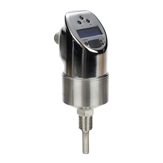
ProSense ETS Series Digital Temperature Sensors
Part Number
ETS50N-30-1001
ETS50N-50-1001
ETS50N-100-1001
ETS50N-150-1001
ETS25N-30-1001
ETS25N-50-1001
ETS50N-30-1003
ETS50N-50-1003
ETS50N-100-1003
ETS50N-150-1003
ETS25N-30-1003
ETS25N-50-1003
* Only one output can be configured as analog.
o
PeraTing
S
eTS S
enSe
T
emPeraTure
Measuring
Thread
Range
Size
1/2"
MNPT
1/4"
MNPT
-58 to 302°F
(-50 to 150°C)
1/2"
MNPT
1/4"
MNPT
i
nSTrucTionS
erieS
S
enSorS
Length
Output
30mm
Output 1: switch
50mm
PNP, N.O./N.C.,
selectable or
100mm
4-20 mA*
Output 2: switch
150mm
PNP, N.O./N.C.,
selectable or
30mm
4-20 mA*
50mm
30mm
50mm
Output 1: switch
PNP, N.O./N.C.,
100mm
selectable
Output 2: switch
150mm
PNP, N.O./N.C.,
selectable
30mm
50mm
Advertisement
Table of Contents

Related Manuals for Prosense ETS25N-50-1001


Summarization of Contents
Document Information
Notes on Safety Conventions and Icons
Explains safety symbols and their meanings used in the manual for clear understanding of warnings and notices.
Basic Safety Instructions
Designated Use
Defines the intended purpose of the ProSense ETS Series digital temperature sensor and its application.
Installation, Commissioning and Operation
Outlines requirements for installation, commissioning, and operation by qualified and authorized personnel.
Operational Safety
Details general safety requirements and standards met by the device, including functional safety aspects.
Certificates and Approvals
Lists compliance with CE, UL, and other relevant safety standards and approvals for the device.
Installation
Installation Conditions
Provides crucial notices and precautions for installing the sensor correctly into the process connection.
Mounting the Device
Describes various options and general instructions for mounting the sensor in pipes for optimal temperature monitoring.
Operating Options
On-Site Operation
Explains how to program and operate the device directly using its keys and display interface.
Navigating in the Operating Menu
Details the step-by-step process for navigating the device's operating menu and accessing parameters.
Structure of the Operating Menu for 2x Switch Outputs
Illustrates the menu structure for configuring devices with two switch outputs, detailing available functions.
Structure of the Operating Menu for 1x Switch Output and 1x Analog Output (4 to 20mA)
Shows the menu structure for devices with one switch and one analog output, detailing available functions.
Basic Settings
Covers fundamental configuration parameters like technical units, zero point adjustment, and display settings.
Settings for Output - 2x Switch Output
Explains configuration options for hysteresis, window function, and contact types for two switch outputs.
Settings for Output - 1x switch output and 1x analog output (4 to 20mA)
Details settings for configuring one switch and one analog output, including switching characteristic and delay times.
Settings for Service Functions
Covers service-related functions such as locking, device reset, revision counter, and simulation modes.
Programming with XT-SOFT Software
Describes how to use the XT-SOFT software for advanced programming and configuration of the ETS Series devices.
Additional Operating Options
Lists read-only information available via XT-SOFT software, such as device status, serial numbers, and firmware versions.
Diagnostics and Troubleshooting
Diagnostic Information on Local Display
Explains how to interpret diagnostic information shown on the device's local display and status LED for error identification.
Need help?
Do you have a question about the ETS25N-50-1001 and is the answer not in the manual?
Questions and answers