Table of Contents
Advertisement
P
ro
D
igiTal
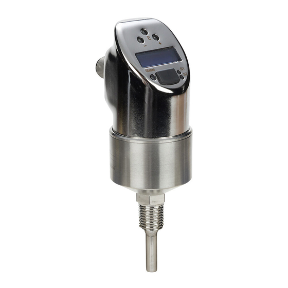
ProSense ETS Series Digital Temperature Sensors
Part Number
ETS50N-30-1001
ETS50N-50-1001
ETS50N-100-1001
ETS50N-150-1001
ETS25N-30-1001
ETS25N-50-1001
ETS50N-30-1003
ETS50N-50-1003
ETS50N-100-1003
ETS50N-150-1003
ETS25N-30-1003
ETS25N-50-1003
* Only one output can be configured as analog.
o
PeraTing
S
eTS S
enSe
T
emPeraTure
Measuring
Thread
Range
Size
1/2"
MNPT
1/4"
MNPT
-58 to 302°F
(-50 to 150°C)
1/2"
MNPT
1/4"
MNPT
i
nSTrucTionS
erieS
S
enSorS
Length
Output
30mm
Output 1: switch
50mm
PNP, N.O./N.C.,
selectable or
100mm
4-20 mA*
Output 2: switch
150mm
PNP, N.O./N.C.,
selectable or
30mm
4-20 mA*
50mm
30mm
50mm
Output 1: switch
PNP, N.O./N.C.,
100mm
selectable
Output 2: switch
150mm
PNP, N.O./N.C.,
selectable
30mm
50mm
Advertisement
Table of Contents

Related Manuals for Prosense ETS50N-50-1001


Summary of Contents for Prosense ETS50N-50-1001
- Page 1 S enSe erieS igiTal emPeraTure enSorS ProSense ETS Series Digital Temperature Sensors Measuring Thread Part Number Length Output Range Size ETS50N-30-1001 30mm Output 1: switch ETS50N-50-1001 50mm PNP, N.O./N.C., 1/2” selectable or MNPT ETS50N-100-1001 100mm 4-20 mA* ETS50N-150-1001 Output 2: switch 150mm PNP, N.O./N.C.,...
-
Page 2: Table Of Contents
User Manual - ETS Series Digital Temperature Sensors 1 Document Information ������������������������������������������������������������������������������������������3 1.2 Notes on Safety Conventions and Icons .................. 3 2 Basic Safety Instructions ����������������������������������������������������������������������������������������3 2.1 Designated Use ........................3 2.2 Installation, Commissioning and Operation ................3 2.3 Operational Safety ........................3 2.4 Certificates and Approvals ...................... -
Page 3: Document Information
2 Basic Safety Instructions 2.1 Designated Use The ProSense ETS Series digital temperature sensor is for monitoring, displaying and regulating process temperatures. The device has been safely built with state-of-the-art technology and meets the applicable requirements and European Community (EC) Directives. -
Page 4: Certificates And Approvals
User Manual - ETS Series Digital Temperature Sensors • Hazardous Locations The ProSense ETS Series is not approved for use in Hazardous Locations. 2.4 Certificates and Approvals CE mark, declaration of conformity The device is designed to meet state-of-the-art safety requirements and left the factory in a condition in which it is safe to operate. -
Page 5: Electrical Connection
5 Operating Options 5.1 On-Site Operation The ProSense ETS Series is programmed and operated by means of three keys or by using XT-SOFT programming software (see the Programming with XT-SOFT Software section of these instructions). The digital display and the light emitting diodes (LEDs) support navigation in the operating menu. -
Page 6: Navigating In The Operating Menu
User Manual - ETS Series Digital Temperature Sensors 5.2 Navigating in the Operating Menu BASE > 3 s SAVE > 3 s A Function group selection B Function selection 1. Enter the operating menu. Press the E key for longer than 3 seconds. -
Page 7: Structure Of The Operating Menu For 2X Switch Outputs
User Manual - ETS Series Digital Temperature Sensors 5.3 Structure of the Operating Menu for 2x Switch Outputs BASE UNIT °C °F ZERO GET’Z DISP PVRO SPRO OFFR DESI FUNC WINC HYNC WINO HYNO TRSP OUT2 FNC2 WINC HYNC WINO... -
Page 8: Structure Of The Operating Menu For 1X Switch Output And 1X Analog Output (4 To 20Ma)
User Manual - ETS Series Digital Temperature Sensors 5.4 Structure of the Operating Menu for 1x Switch Output and 1x Analog Output (4 to 20mA) Devices with analog output either output 1 or output 2 can be configured as an analog output. -
Page 9: Basic Settings
User Manual - ETS Series Digital Temperature Sensors 5.5 Basic Settings Function Function Settings Description Group °C Select technical unit: °C, °F, K Technical unit UNIT °F Factory setting: °F Configure zero Position adjustment: within ±18ºF/K ZERO 0 . 0 point (±10ºC) of the upper range limit... - Page 10 User Manual - ETS Series Digital Temperature Sensors • Factory setting: Switch point SP 1: 113.0°F (45°C); Switch-back point RSP 1: 112.1°F (44.5°C) Switch point SP 2: 131.0°F (55°C); Switch-back point RSP 2: 130.1°F (54.5°C) • Range of adjustment LRL = Lower Range Limit...
-
Page 11: Settings For Output - 1X Switch Output And 1X Analog Output (4 To 20Ma)
User Manual - ETS Series Digital Temperature Sensors 5.7 Settings for Output - 1x switch output and 1x analog output (4 to 20mA) Function Function Settings Description Group WINC: window/NC contact HYNC: WINC hysteresis/NC contact HYNC WINO: Switching FUNC WINO... - Page 12 User Manual - ETS Series Digital Temperature Sensors Function Function Settings Description Group -58 to 266°F (-50 to 130°C) Value for 4mA Lower range value in increments of SETL 0 . 0 (LRV) 0.18°F (0.1°C) Factory setting: 32.0°F (0.0°C) -22 to 302°F (-30 to 150°C)
-
Page 13: Settings For Service Functions
User Manual - ETS Series Digital Temperature Sensors 5.8 Settings for Service Functions Function Function Settings Description Group Enter the locking code for enabling the Locking code LOCK device. Freely selectable code 1...9999. 0 = no locking Change locking CODE... -
Page 14: Programming With Xt-Soft Software
User Manual - ETS Series Digital Temperature Sensors 5.9 Programming with XT-SOFT Software The ETS Series can be programmed using XT-SOFT programming software, available as a free download at www.automationdirect.com, and an XT-USB configuration cable (purchased separately). The operating options listed in the previous “On-Site Operation”... - Page 15 User Manual - ETS Series Digital Temperature Sensors • E-code for errors In the event of an error message, the measured value is uncertain. • W-code for warnings In the event of a warning, the measured value is reliable. Code...
-
Page 16: Maintenance
User Manual - ETS Series Digital Temperature Sensors 7 Maintenance Any buildup on the sensor can have a negative effect on the sensor response time. For this reason, check the sensor for buildup at regular intervals. Removing the device Make sure the process is unpressurized before you remove the device! Do not twist the device out of the process connection thread at the housing.
Need help?
Do you have a question about the ETS50N-50-1001 and is the answer not in the manual?
Questions and answers