Table of Contents
Advertisement
VAIE 2000
Voice Alarm Integrated Systems
VAR 2006 Router
VAC 2006 Controller
MANUALE DI ISTRUZIONI
OPERATING MANUAL
FBT ELETTRONICA S.p.A. - Via Paolo Soprani, 1 - ZONA IND. SQUARTABUE - 62019 RECANATI (MC) - ITALY
TEL. 071750591 r.a. - FAX 0717505920 - P.O. BOX 104 - E-mail: info@fbt.it - www.fbt.it
Advertisement
Table of Contents

Related Manuals for Fbt VAC 2006


Summarization of Contents
Introduction to FBT VAIE 2000 System
System Overview
Provides a general description of the VAIE 2000 product range for emergency services.
General Description of VAC 2006 and VAR 2006
VAC 2006 Controller Overview and Components
Describes the front and rear panels, including buttons, sockets, and their functions.
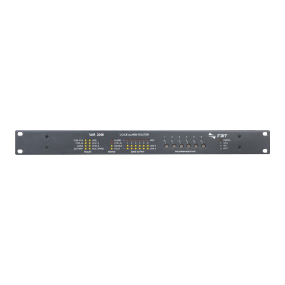
VAR 2006 Router Overview and Features
Details the front panel components and main features of the VAR 2006 router.
Key Features of the VAC 2006 Controller
Lists the primary features and functionalities of the VAC 2006 controller.
Key Features of the VAR 2006 Router
Lists the primary features and functionalities of the VAR 2006 router.
VAC 2006 Controller Control Panel Functions
Explains the function of each control element on the VAC 2006 controller's front panel.
Warnings, Safety, and Installation Guidelines
Power Supply and Earthing Requirements
Details essential information regarding the equipment's power supply and proper earthing connections.
Essential Safety Notes and Precautions
Provides critical safety instructions for handling and maintaining the equipment.
Installation Guidelines and Ventilation
Covers installation requirements, compliance with standards, and proper ventilation for the equipment.
System Connections Guide
Connecting Controllers
Explains how to connect multiple VAC 2006 controllers using Cat.5e SF/UTP cables.
Connecting Output Lines
Details connecting output lines from VAC 2006 to VAR 2006 routers and DPU amplifiers.
Connecting Emergency Stations
Guides on connecting FMD 2001/2012 emergency stations to the VAC 2006 controller.
Connecting Audio Inputs
Explains how to connect BGM and PA sources to the VAC 2006 audio inputs.
RJ45 Input Contacts for Control
Describes the RJ45 socket for 7 monitored digital control inputs.
Connecting External Power Supply
Details the terminals for connecting a 24 VDC external power supply.
Operating Conditions and System Terminology
General Definitions and System States
Defines system operating conditions, signalling modes, and general terms used in the manual.
Signalling of Operating Conditions
Explains how the VAC 2006 system signals various operating conditions like Quiescent, Alarm, and Fault.
Glossary of System Terms
Provides definitions for terms like BGM Source, PA Source, and Emergency Source.
Equipment and Functional Specifications
VAC 2006 Controller Technical Specifications
Lists detailed technical specifications for the VAC 2006 controller, including inputs, outputs, and power.
VAR 2006 Router Technical Specifications
Lists detailed technical specifications for the VAR 2006 router, including power, output, and dimensions.
VAC 2006 Controller Control Panel Functions
Explains the function of each control element on the VAC 2006 controller's front panel.
System Configuration Guide
Introduction to System Configuration
Explains the purpose of the Controller Manager software for system compilation and configuration.
Creating a New System Project File
Guides users on how to create a new system configuration project using the software.
Opening an Existing System Project
Provides instructions on how to open a previously saved system configuration project.
Inserting Controllers into the System
Details the process of adding VAC 2006 units to the system configuration.
Configuring Controller Lines and Connected Equipment
Explains how to configure lines for each controller, specifying connected equipment like routers and amplifiers.
Menu Structure and Navigation
Accessing System Option Menus
Explains how to navigate the system menus and access different management panels.
MUSIC Menu: Basic Level Operations
Describes the MUSIC menu for controlling BGM sources and volumes in Quiescent Conditions.
AUDIO SETTINGS Menu: Adjusting Audio Parameters
Details how to adjust audio parameters for PA sources, including speech levels and chime settings.
INSPECTION Menu: System Status Investigation
Provides access for investigating system status, identifying causes of faults or emergencies.
OPERATOR Menu: Managing System Conditions
Allows trained personnel to manage emergency, failure, and disablement conditions with password access.
CONFIGURATION Menu: Advanced System Settings
Enables authorised personnel to modify configuration parameters for system setup and maintenance.
Using the FBT VAIE 2000 System
Initialising the System
Guides on system initialization, password setup, impedance acquisition, and diagnostics.
MUSIC Menu Operations
Explains how to control background music sources, volume, and zone activation.
AUDIO SETTING Menu Operations
Details settings for PA sources, speech levels, chime, and input modes.
INSPECTION Menu Functions
Describes how to check system status, view faults, impedance, configuration, and test indicators.
OPERATOR Menu Functions
Covers system management during emergencies, faults, and disablement conditions.
CONFIGURATION Menu Functions
Provides access to advanced settings like impedance, tolerance, passwords, and service options.
MANUAL EMERGENCY - < EMERGENCY > Menu
Explains procedures for manually managing emergencies from a controller or remote stations.
AUTOMATIC EMERGENCY Activation and Management
Details how the system operates during an automatic emergency initiated by external peripheral units.
Fault Warning Condition Management
System Operation and Signalling
Describes system operation and signalling for normal and fault conditions.
Signalling a Fault Warning Condition
Explains the visual and acoustic signals indicating a system fault.
Resetting Signals After Failure Clearing
Details the procedure for manually resetting failure signals and the buzzer.
Need help?
Do you have a question about the VAC 2006 and is the answer not in the manual?
Questions and answers