
Related Manuals for Fbt DLM 260


Summary of Contents for Fbt DLM 260
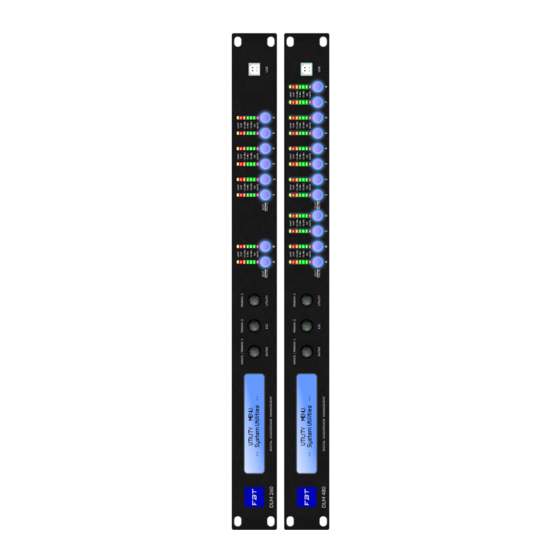
- Page 1 DLM 260 / DLM 480 DIGITAL LOUDSPEAKER MANAGEMENT OPERATING MANUAL Code: 46555 M A D E I N C H I N A...
-
Page 3: Table Of Contents
32 on-board presets are not sufficient. A very useful func on is the ability to recall en re output channel configura ons and a comprehensive library of output files for FBT products is available making it very quick ans easy to create exactly the configura on you need. -
Page 4: Waste-Disposal
WASTE - DISPOSAL Where affixed on the equipment or package, the barred waste bin sign indicates that the product must be separated from other waste at the end of its working life for disposal. At the end of use, the user must deliver the product to a suitable recycling centre or return it to the dealer when purchasing a new product. -
Page 5: Safety Instructions
FBT strongly recommends that this equipment be installed only by a professional sound installer or contractor. • Read these instruc ons •... -
Page 6: Install
INSTALL AC POWER INPUT The AC voltage provided by the audio processor with built-in global voltage opera on must be within ±10% of the specified line voltage (90/240V~). The third pin (grounding pin) on the power cord that comes with the package is a necessary safety component;... -
Page 7: Front Panel
PARAM.1/ENTER controls; when pressed the bu on func on a u lity menu is entered for the DLM 260 / DLM 480 general se ng ( the naviga on within the several "u lity" menus is done using the PARAM.1/PARAM.2 knobs. -
Page 8: Rear Panel
OUTPUTS INPUTS CAUTION DLM 260 AC 90-240V 50/60Hz Designed in Italy by FBT Ele ronica SpA Made in China max. 30W ETHERNET RS 485 1) ON/OFF power switch. 2) AC power input, standard C13 interface; please ensure that the grounding pin of the power supply is well grounded, otherwise an electric shock accident may occur. -
Page 9: Settings
SETTINGS SYSTEM SETTINGS LINK INPUT U lity general menu contains 3 sub-menu system se ngs; under UTILITY For the linked input channel modify the se ngs of any one of the linked MENU turn the PARAM1 naviga on key to select System u li es. channels and the other linked channels will synchronously modify the same value. - Page 10 SETTINGS Knob PARAM2 selects the 1234 channnel, turn PARAM3 to the right to RECALL MODE (MUTE SAFETY) turn on and turn PARAM3 to the le to turn off the linkage. When this mode is turned on, the current channel mute state will be For example, if you need to link output channels 3 and 4, the opera on maintained regardless of reading any preset and only the muted state of the sequence is:...
- Page 11 SETTINGS VIEW FIRMWARE VERSION For example read the preset 3 from the machine You can check the firmware version of the current processor, you can go to Press U lity the our website to download the latest version of the firmware to get •...
- Page 12 DEVICE NAME ENTER NETWORK UTILITY Device Name Device Name Name = DLM 260 PUSH The model of the machine is displayed by default, if you need to modify it NETWORK OPTIONS please follow the following order: Under the se ngs, turn the PARAM1 knob, the last op on is the network •...
- Page 13 SETTINGS IP ADDRESS The level meter of the input channel shows the pre-fader level, that is, it is Only the IP Address is displayed here and the default is automa c not affected by mute; the level meter of the output channel shows the post- acquisi on and the real address will be displayed a er the connec on is fader level and the level is not displayed a er the mute.
- Page 14 SETTINGS NOISE GATE When adjus ng the maximum allowable gain the adjustment step of the The noise gate can appropriately suppress the obvious background noise knob PARAM2 is 1 dB and the adjustment step of PARAM3 is 0.1 dB. caused by the accumula on of front-end equipment or improper system se ngs.
- Page 15 SETTINGS PARAM. 2 DELAY CH - A RMS Cmp CH - A RMS Cmp The input part can provide a maximum delay of 340 milliseconds, which can Threshold = -10.0 dBu Threshold = +20.0 dBu be used to delay the alignment of the tower speaker and the main amplifier speaker with a maximum distance of 115 meters.
- Page 16 SETTINGS FIR FILTER PEQ 1-31 The input channel allows the use to use a 512 taps FIR filter, its opera ng Specific turning of each band of parametric equaliza on, a er Enter, you sampling rate is 48kHz. But do not do any processing for the signal a er can rotate PARAM1 to select the filter type, you can select high and low 24000Hz, keep it as it is.
- Page 17 SETTINGS EDIT OUTPUT CHANNEL INPUT MATRIX EDIT bu on click into the lower level processor can edit the table The input matrix allows the user to mix 2 input signals to any output processing module output channels. channel in any ra o. The knob PARAM1 selects the AB input source and the Long press the Edit bu on to mute the current channel, the level meter of PARAM3 adjusts the gain amount, which can be adjusted from -30 to 0 dB.
- Page 18 SETTINGS GAIN RMS COMPRESSOR The controllable gain range is from -18 to +12dB in 0.1dB steps. It is mainly used to limit the RMS power of the unit. It needs to cooperate with the AES power provided by the unit manufacturer and the amplifica on factor of the power amplifier to calculate the threshold;...
- Page 19 Raylei/Bessel/Bu erworth with a maximum slope of 48dB / oct. Knee = 0 % • Linear phase IIR filter, using FBT exclusive algorithm, retains the shape of the Linkwiz-Raylei/Bessel/Bu erworth filter types without phase distor on, maintaining the linear phase and controlling the me delay at The so and hard inflec on point can be adjusted among which 0% is the...
- Page 20 SETTINGS The so ware contains 4 combina ons of filter forms, including IIR / LIN When the combina on of IIR and FIR filter is selected, the highest slope of (Linear phase filter) / FIR / IIR+FIR four combina ons are op onal. When a IIR filter is -24dB/oct and only 4 band PEQ are available.
- Page 21 SETTINGS PEQ 1-8 OUTPUT MATRIX Specific turning of each stage of parameter equaliza on, a er enter, you The output matrix allows the user to mix output channel signal to any can rotate PARAM1 to select filter type, you can rotate high and low physical output channel in any ra o.
- Page 22 SETTINGS PEQ 1-8 CONNECTING TO A DEVICE Minimum system requirements for running DLM 260/480 so ware: Opera ng system Microso Windows • Using a network cable to connect it is the most direct and safe way of Single core 2.0 GHz connec ng.
-
Page 23: Overview Of Signal Processing
OVERVIEW OF SIGNAL PROCESSING... -
Page 24: Connections
CONNECTIONS CONNECT WITH USB When using only one processor you can use DHCP to connect to the When using the USB interface, directly connect to the USB port of the PC processor. The specific methods are as follow: with a B-type cable , add USB to the so ware and select the corresponding The PC does not need to change the se ngs by default, directly connect model. - Page 25 fixed IP and use a different IP address. FIRMWARE UPGRADE When FBT releases a new version of the firmware, users can download the latest firmware from the official website. You can use TCP/IP to upgrade the firmware to ensure the stability of the power supply during the upgrade process.
- Page 26 CONNECTIONS Tick the input channels that need grouping control, you can freely group the input channels, you can create a new group to control the remaining ungrouped channels, click Add a er the selec on is complete. At this me there is a small window for group control, you can control the overall gain, mute, monitor level,etc...
-
Page 27: Software
SOFTWARE HOME PAGE OVERVIEW Enter the main page of the so ware, the upper le corner respec vely shows: New / Import / Save project Add device For the case of a known machine with a fixed IP address / USB / RS485, use to add the corresponding device for online opera on. - Page 28 SOFTWARE SOFTWARE MAIN INTERFACE On the main interface of the processor the overall status of the audio paths rou ng and the order of the signal processing modules are displayed. Note: the signal processing modules here cannot be directly clicked to access, need to be modified separately in the corresponding input or output channels. Load &...
- Page 29 SOFTWARE CHANNEL FUNCTIONS COPY: select (highlight) the channel SETTINGS: LAN, RS485, channel label, group se ng, recall to be copied, and select the func on to be copied at the same mode, user authority, administrator password, output an - type, then the required func on can be copied to the overflow and other se ngs.
- Page 30 SOFTWARE RS 485: Set the COM ID of RS485, the default is 01, the maximum is 32. GROUP RESET: a er using the group, the last saved group informa on is s ll in the input channel. If you need to remove it, you need to reset the required channelsin the group reset.
- Page 31 SOFTWARE USER AUTHORITY SETTING: when logging in as an administrator, part or For example: now the administrator has logged in, select all locked items all of the output channel func ons of the machine can be locked to ensure and hide them. the integrity of the preset.
- Page 32 SOFTWARE ADMINISTRATOR SETTINGS: modify the administrator password The same applies to dual-channel, that is, two channels can be applied with plug-ins and the corresponding FIR with a sampling rate of 96kHz needs to be used, and the FIR generated by a third party can be imported here (Note: the FIR filter of the input and output channels runs at 48kHz sampling rate, the audio stream is processed by FIR through down-sampling and then up- sampled back to the DSP processing chain.
- Page 33 fixes, new func ons, etc... At present , this func on needs to be connected via a network cable. To get the latest firmware you can visit FBT official website. FW Update When using the USB/RS485 connec on clicking on the firmware upgrade will pop up such a prompt.
- Page 34 SOFTWARE LOGIN: Administrator login, the administrator has the highest Advanced generator provides a choice of insert posi on, management authority of this which can be selected before the input channel processing (a er A/D), a er the input channel processing or output (before D/A) when the input channel is selected a er processing or output (before D/A), when select INPUT PRE- PROC, there are two noises: pink noise / white noise.
- Page 35 SOFTWARE SIGNAL ROUTING PART SIGNAL FLOW CHART: Indicate the processing path a er analog signal input A/D conversion, including rou ng status, plug-in status, etc..It is only for display and cannot be clicked to enter the modifica on. If you need to make changes you can make detailed modifica ons in the input and output interface. In the input matrix you can arbitrarily route the signal from the input processing channel to the output processing channel.
- Page 36 SOFTWARE In example, use the processor A channel input, the output channel 1 is The specific method is to assume that the output channels need to be connected to a 2 way passive speaker and the route is a shown in the above linked.
- Page 37 SOFTWARE INPUT PART Input channel processing includes noise gate, DLf, equalizer, compressor, delay. PROCESS 1 DYNAMIC LOUDNESS FILTER: Working principle: according to the human ear equal loudness curve when the sound pressure is low, the ultra-low and ultra-high frequencies are increased;...
- Page 38 SOFTWARE PROCESS 2 VARIABLE EQUALIZER CONFIGURATION CONTAINS FOUR CATEGORIES. Note: This FIR filter is 48kHz sampling rate 512 taps. Since the overall sampling rate is 96kHz , the sampling rate will down to 48kHz before FIR and a er processing, the sampling rate will be re-extended back to 96kHz. 31 BANDS OF PEQ.
- Page 39 SOFTWARE PROCESS 3 COMPRESSOR: Conven onal compressors will provide: The Delay alignment op on is provided in the lower right corner of the threshold, a ack me, ra o, release me, gain compensa on, so and hard so ware, which can be used to align the delays generated by FIR filters with different latency applied to the different channels.
- Page 40 SOFTWARE OUTPUT SECTION The overall overview of the output sec on including crossover, polarity, delay, gain, equalizer, RMS compressor, peak limiter, hard limiter, etc.. Process 1. Linear phase filter / FIR filter / FIR + IIR The conven onal IIR filter maintains the slope of the analog filter, but will produce a phase devia on. The higher the order, the more the phase shi , which in turn causes magnitude problems.
- Page 41 SOFTWARE In the high and low pass filters of IIR we provide three types of tradi onal The Linear Phase Filters replicate exactly the slope of the analog filter Bu erworth / Linkwitz-Riley / Bessel slopes ranging from -6dB/oct to - (LR24 / LR48), there by keeping the phase Linear and easily coupling the 48dB/oct.
- Page 42 SOFTWARE For the FIR filter two modes can be selected, FIR+8 segment PEQ, FIR+IIR Provides three guides of high-pass / low-pass / band-pass, you can enter high and low pass with a slope of up to -24dB + 4 segment PEQ. the frequency that needs to be band-passed according to your needs, choose more or less taps, slopes from -20dB to -120dB/oct, and mul ple window func on types.
- Page 43 SOFTWARE The output part provides three levels of compression limiter se ngs, namely RMS compressor, which can be used to set the compression op on of the average level over a period of me. When the compression ra ois high, it is the limiter. The peak limiter has a very low a ack me and quickly suppresses the burst signal.
-
Page 44: Specifications & Data
SPECIFICATIONS & DATA GENERAL________________________________________________ PROCESSING___________________________________________________________ Input Impedance 20K Ohm balanced Signal Generator White/Pink noise - Level range: -30dBu +10dBu Output Impedance 100 Ohm Input & Output Gain -18dB +12dB, step 0.1dB Max. Input Level +20dBu Noise Gate Threshold: -80dBu -45dBu Max.
Need help?
Do you have a question about the DLM 260 and is the answer not in the manual?
Questions and answers