
Related Manuals for CREVIS GT-5232


Summarization of Contents
1. Important Notes
1.1. Safety Instructions and Precautions
Provides essential safety guidelines, symbols, and certifications for the product's safe operation.
2. Product Specifications
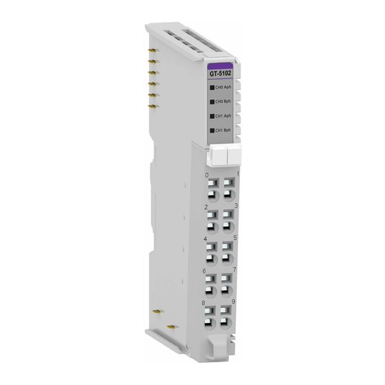
2.1. GT-5102 Model Specifications
Details for the GT-5102 model, including wiring diagrams, LED indicators, and specifications.
2.2. GT-52xx Series Specifications
Overview and specifications for GT-5211, GT-5212, GT-5221, GT-5231, and GT-5232 modules.
2.3. General Specification Summary
General specification details covering transfer channels, rate, data bits, and buffer sizes for the GT-52xx series.
3. Environment Specification
3.1. Operating Conditions and Certifications
Details operating temperature, humidity, vibration resistance, and product certifications.
4. Configuration and Operation
4.1. GT-52xx Data Mapping
Details input and output image data mapping for GT-52xx series modules, including status and control bits.
4.2. Configuration Parameter Data
Configuration parameter data for 1-channel and 2-channel modules (GT-5211, GT-5221, GT-5231, GT-5212, GT-5232).
4.3. Examples of Data Handling
Illustrates transmitting and receiving data, including buffer overrun checks and specific examples like TPR/TPA.
5. Dimensions
5.1. GT-5xxx Series Dimensions
Detailed physical dimensions and drawings for the GT-5xxx series of modules.
6. Mounting and Handling
6.1. I/O Module Insertion and Removal
Procedure for safely inserting and removing I/O modules, detailing locking mechanisms.
6.2. Removable Terminal Block (RTB)
Details on the RTB for convenient maintenance and module combination/removal.
7. G-Bus Pin Description
7.1. G-Bus Connector Pinout Details
Details the pin configuration and function for the G-Bus connector on the modules.
Need help?
Do you have a question about the GT-5232 and is the answer not in the manual?
Questions and answers