Table of Contents
Advertisement
7929 SW Burns Way
Phone: 503 344-5085
Suite F
Wilsonville, OR
sales@cascadiamotion.com
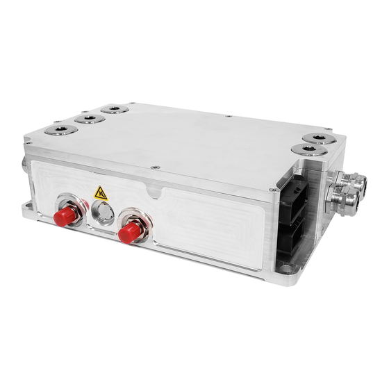
PM/RM/CM200
Hardware User Manual
Revision 3.3
0A-0001-01
Everything you need to know to install, set up, and calibrate the PM and
RM family of AC drives on asynchronous and PM synchronous motors
in your Electric or Hybrid vehicle
1/14/2021
RMS PM Hardware User Manual
1 of 54
Advertisement
Table of Contents

Related Manuals for Cascadia RM300


Summarization of Contents
Installing the PM Drive
Liquid Cooling Connections
Details specifications and requirements for passing liquid through the controller for cooling.
PM100/PM150 External Signal Connectors
Describes the two AMPSEAL connectors for internal I/O on PM100/PM150 units.
PM250 External Connections
Details the two circular connectors (J1 and J2) for external connections on the PM250.
RM100 Signal Connections
Explains the single 35-pin Ampseal connector for I/O signals on the RM100.
RM300 Signal Connections
Details the two connectors for low voltage I/O and motor signals on the RM300.
PM500 Signal Connections
Describes the three connectors for low voltage I/O signals on the PM500.
CM200 Signal Connector
Covers the Molex CMC 48-way connector for all low voltage signals on the CM200.
External Power Connections
Details how to connect external power sources to the controller.
DC+ / DC-
Details DC/Battery power input via two wire ports on the controller.
Phase A / Phase B / Phase C
Explains wiring motor phases A, B, C for proper rotation and EMI reduction.
Pre-Charge Circuit
Describes the external circuit needed to limit inrush current to the controller's capacitors.
Main Contactor
Identifies the main switching element for DC high-voltage power source connection.
Main Fuse
Specifies the requirement for fusing the DC power input to protect against short circuit currents.
Passive Discharge of the High Voltage DC Bus
Explains how internal resistors passively discharge the DC bus capacitance after power removal.
12V Power
Details the requirement for a 12V power source for controller operation and setup.
Grounding
Explains how to connect the inverter housing to ground for safety and proper operation.
Typical Application Wiring Diagram
Provides an overview of common wiring diagrams covered in the manual.
Controller 12V Power Wiring
Details two configuration methods for controller 12V power wiring.
Pre-charge Circuit
Provides a schematic for the pre-charge circuit, detailing its components and connections.
Analog/Digital Vehicle Control
Explains how analog/digital signals control inverter operation, noting RM100 limitations.
Motor Control (Typical Wiring)
Shows typical wiring diagrams for induction and PM motor control interfaces.
CAN Interface
Describes the controller's active CAN interface for motor control, diagnostics, and configuration.
RS-232 Interface
Details the RS-232 serial interface for setup, tuning, and software updates.
Encoder Interface (Not included on RM100/RM300)
Explains the position encoder interface for induction motor speed and angle calculation.
Resolver Interface
Discusses the resolver interface, a position sensor for Permanent Magnet motors.
Vehicle Interface Setup
Analog Inputs
Details the analog inputs available on different units for general sensing and RTD measurements.
Digital Inputs
Describes up to 8 digital inputs for vehicle interface and feedback from contactors/switchgear.
Digital Outputs
Covers up to 6 available digital outputs, detailing their types and functions.
Need help?
Do you have a question about the RM300 and is the answer not in the manual?
Questions and answers