Sign In
Upload
Download
Table of Contents
Contents
Add to my manuals
Delete from my manuals
Share
URL of this page:
HTML Link:
Bookmark this page
Add
Manual will be automatically added to "My Manuals"
Print this page
×
Bookmark added
×
Added to my manuals
Manuals
Brands
Rotex Manuals
Controller
THETA RS
Product documentation
Rotex THETA RS Product Documentation
Hide thumbs
1
2
Table Of Contents
3
4
5
6
7
8
9
10
11
12
13
14
15
16
17
18
19
20
21
22
23
24
25
26
27
28
29
30
31
32
33
34
35
36
37
38
39
40
41
42
43
44
45
46
47
48
49
50
51
52
53
54
55
56
57
58
59
60
61
62
63
64
65
66
67
68
69
70
71
72
73
74
75
76
77
78
79
80
81
82
83
84
85
86
87
88
89
90
91
92
93
94
95
96
97
98
99
100
101
102
103
104
105
106
107
108
109
110
111
112
113
114
115
116
117
118
119
120
121
122
123
124
125
126
127
128
129
130
131
132
133
134
135
136
137
138
139
140
141
142
143
144
145
146
147
148
149
150
151
152
153
154
155
156
157
158
159
160
161
162
163
164
165
166
167
168
169
170
171
172
173
174
175
176
177
178
179
180
181
182
183
184
185
186
187
188
189
190
191
192
page
of
192
Go
/
192
Contents
Table of Contents
Troubleshooting
Bookmarks
Table of Contents
Table of Contents
1 Softwareversion
2 General Safety Instructions
Application
Conditions for Start-Up
Safety Measures for EMC - Conform Installation
Cable Dimensions and Maximum Cable Length
Maximum Cable Lengths
Grounding and Neutralizing
Domestic Hot Water Higher than 60 °C
Connecting Accessories
Service and Cleaning
3 Overview
4 List of Abbreviations
5 Operation
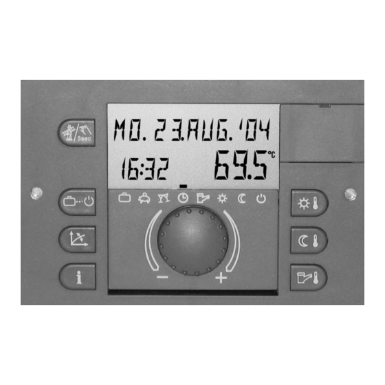
User Interface
Basic Display
Operating Elements
Rotary Pushbutton (Press/Turn)
Daytime Room Temperature" Key
Night-Time Room Temperature" Key
Daytime DHW Temperature" Key
Operating Mode" Key (Basic Display)
Heating Curve" Key
Plant Information" Key
Emission Measurement / Manual Mode" Key
Code-Input
Installer Code and OEM Code
User Code
Automatic Exit Time
Automatic Return Time
Menu Selection Level
Level and Parameter Overview
Time - Date" Menu
Time Program" Menu
Control Circuit Selection
Program Selection
Weekday and Cycle Selection
Programming Time Programs and Cycle Temperatures
SYSTEM Level (Parameter)
Language
Time Programs
Control Mode
Summer Switch-Off
Reset Parameter
DHW Level
Hot Water Economy Temperature
Legionella Protection Day
Unmixed Circuit / Mixed Circuit 1 / Mixed Circuit 2 Menu
Reduced Mode
Heating System
Malfunction Messages
Parameter Settings
HYDRAULIC Level
SYSTEM Level
DOMESTIC HOT WATER (Type
Selection Levels Unmixed Circuit / Mixed Circuit 1 / Mixed Circuit 2
Heat Generator Level
Raising Return Temperature Level
Solar Level
Solid Fuel Level
Buffer Level
CASCADE CONTROL Level
BUS Level
RELAY TEST Level
ALARM Level
Level SENSOR ADJ
6 General Functions
Starting up
Controller Configuration
Complete Reset
Basic Settings and Parameter Preselection
Switching Time Program Enabling
Suppressing the Cycle Temperature on Time Program Level
Eanbling Separate Operating Modes and Temperature Changes
Selection of Hydraulic Parameter Presettings
Variable Adaptation of Hydraulic Parameters (Variable Inputs and Outputs)
Temperature Display in Fahrenheit
Controller Type Code
7 General Controller Functions
Outside Temperature Measurement
Determination of Long-Time Value and Mean Value
Building Type
Heating Circuit Outside Temperature Assignment (Outdoor Sensor 2)
Error Display Outdoor Sensor During MCBA Operation
Climate Zone
Summer Switch-Off
System Frost Protection
Pump and MIX Valve Forced Operation (Anti-Blocking Protection)
8 Hydraulic Components and Their Functions
Heat Generator: Boiler
Heat Generator Start-Up Protection
Heat Generator Minimum Temperature Limit
Heat Circuits Minimum Temperature Limit
Heat Generator Maximum Temperature Limit
Heat Generator Sensor Mode
Minimum Burner Run Time
Modulation P-Band (Xp)
Modulation Sample Time Ta
Modulation Integral Action Time Tn
Modulation Running Time
Modulation Starting Time
Modulation Starting Load
Control of Communicating Heat Generators (H-GEN Type 5)
Flue Gas Temperature Monitoring
Charging Pump (CHP)
Primary Pump (PP)
Boiler Circuit Pump
Parallel Heat Generator Release (PHR)
Return Control
Bypass Pump
Return Control through Controlled Flow Mixing
Indirect Return Control
When to Activate Boiler Sensor 2
External Heat Generator Disable
Adjustment of the Heat Generator According to the Common Flow Temperature
Features of Fuel Value Heat Generator Via Data Bus (MCBA) (..C
DHW Charging in Boiler Control MCBA
DHW Operation in Combined Devices
Heat Generator Forced Dissipation
Operating Hours Counter
Heating Circuit
Weather Controlled Heating Operation
Heating Characteristic Curve
Heating Circuit Reduced Mode
Heating System (Exponent)
Heating Circuit Temperature Limitation
Heating Circuit Parallel Shift
Screed Function
Assessment of the Room Temperature / Room Influence
Heating Circuit with Room Influence
Room Factor Heating Circuit
Room Controller Heating Circuit
Heating Curve Adaptation Heating Circuit
Heating Circuit Room Frost Protection Limit
Heating Circuit Switch-On Optimisation
Optimisation for Room Controller (RC)
Mixer Control
Proportional Band Xp
Integral Action Time Tn
Sample Time Ta
Actuator Running Time
Function Heating Limit
Domestic Hot Water Control
DHW Tank Loading (DHW)
Circulation Pump (CIR.)
Electrical Heating Element (ELH)
Solid Fuel Loading Pump (SFP)
Tank Charge Changeover
Heat Forced Dissipation Valve
Hydraulic Buffer Release (HBR)
Heating Circuit Constant Temperature Control
Fixed Value Control
Demand Contact
Global Malfunction Message Output
Global Malfunction Message Input
Timer
External Switching Modem
External Information
9 Data Bus / Bus Communication / Room Controllers
The Data Bus System
Data Bus Addresses
Control Functions Via the Bus
Boiler Corrosion Protection
Indirect Return Temperature Control
Accumulator Mode (Accumulator Priority Mode)
Heating Demand
Clock Synchronisation
Room Temperature Information
Errors/ Status Indications
Operation with Wall Device RFF
Bus Priority Heating Circuit
Expanding the System by Several Standard Units
Examples with Several Controllers
Unrestricted Use of Gateway GWK
10 Cascading of Heat Generators in the Bus System
General Description of Cascading of Control Devices
Functions of the Cascade Parameter
Mode of Operation of Cascade Control
Switch-Off Behavior
Operation with Boiler Control (Old)
Operation with Conventional Heat Generators (2-Point)
Operation with Boiler Control (New)
Operation with Group Reversal
Behavior During Heat Generator Fault
11 Help for Commissioning, Maintenance and Problem Solving
Automatic Set-Function
Check Safety Temperature Limiter
Relay / Function Test
Malfunction Messages
Error Messages Basic Display / Error Stack
OEM-Information for Troubleshooting
Controller Complete Reset
Controller Time Correction
Sensor Calibration
12 Mounting
Mounting Instructions for NORM Type
Electrical Installation
Mounting Instructions for UNIT Type
Mounting UNIT
Electrical Installation
Electrical Connection
Mounting Instructions for Mounting with Wall Socket MS-K
Electrical Installation
Electrical Connection in Wall Socket MS-K
Mounting Instructions Remote Unit
Mounting Location
Electrical Connection
Data Bus Addressing
Mounting Instructions Wall Device RFF
13 Accessories
Outdoor Sensor AF
Immersion Sensor KVT
Flow Sensor VF
Flue Gas Sensor / Solar Panel Flow Sensor
14 Technical Data
General
Digital Inputs
15 Index
Advertisement
Quick Links
Download this manual
EbV
Product documentation THETA NORM/UNIT
Product documentation
Controller series THETA
NORM, UNIT, RS and RFF types
Standing: Software version 2.3
Table of
Contents
Previous
Page
Next
Page
1
2
3
4
5
Advertisement
Table of Contents
Need help?
Do you have a question about the THETA RS and is the answer not in the manual?
Ask a question
Questions and answers
Related Manuals for Rotex THETA RS
Controller Rotex Controller Series Product Documentation
(192 pages)
Controller Rotex QTF Series Installation, Operation And Maintenance Manual
Pneumatic rack and pinion actuator (26 pages)
Controller Rotex RoCon HP Operating Instructions Manual
Electronic controller for heat pumps (52 pages)
Controller Rotex HPSU compact 304 System Instructions
Rocon hp (40 pages)
Controller Rotex RoCon UFH Operating Instructions Manual
Single-room temperature controller (56 pages)
Table of Contents
Print
Rename the bookmark
Delete bookmark?
Delete from my manuals?
Login
Sign In
OR
Sign in with Facebook
Sign in with Google
Upload manual
Upload from disk
Upload from URL


Need help?
Do you have a question about the THETA RS and is the answer not in the manual?
Questions and answers