
Subscribe to Our Youtube Channel
Related Manuals for Rotex RoCon UFH


Summary of Contents for Rotex RoCon UFH
- Page 1 For certified companies ROTEX RoCon UFH Operating instructions Single-room temperature controller For the types UFH-BM UFH-UM UFH-RMD2 UFH-RMD6 UFH-RMF2A UFH-RMF6A UFH-RD UFH-RFT Issue 08/2016...
-
Page 2: Table Of Contents
Wired controller module ................14 Wireless controller module................. 15 Room controllers ..................16 Clock module....................17 Details of RoCon UFH according to EN 60730-1:2012-10 ......18 Dimensions....................18 Approvals, tests and conformity..............19 Transport and storage ................... 20 Installation and commissioning ................21 Installing the modules ................ - Page 3 ..............51 ® 10.2 Further information about EnOcean -wireless systems ......54 11 Decommissioning and disposal ................55 12 Spare parts and accessories .................55 13 Warranty ........................55 14 Copyright .......................55 15 Customer satisfaction ....................55 16 Addresses......................55 FA ROTEX RoCon UFH - 08/2016...
-
Page 4: About These Operating Instructions
Explanation of the symbols and displays Symbol Meaning Precondition for an action Action with one step Action with several steps Result of an action Enumeration Text Output on display Highlighting Highlighting Tab. 2: Explanation of the symbols FA ROTEX RoCon UFH - 08/2016... -
Page 5: Safety
Safety Safety 2.1 Use as intended The single-room temperature controller RoCon UFH is suitable solely for regulating (heating/cooling) the room temperature of single rooms with underfloor heating. Any other use is not as intended. 2.2 Foreseeable misuse The RoCon UFH single-room temperature controller must... -
Page 6: Modifications To The Product
Neither the manufacturer nor the distributing company shall be liable if the device is not used as intended. The manufacturer shall not be liable for misprints. FA ROTEX RoCon UFH - 08/2016... -
Page 7: Description Of The Product
Optionally, several controller modules each with 2 or 6 control circuits can be adapted. The RoCon UFH single-room temperature controller is available in 2 variants: Room controllers and controller modules are linked to one an- other via a wire line. -
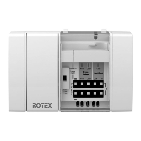
Page 8: Overview Of The Separate Components
Pump relay contact, heating LED red Pump relay contact, cooling (heating pump) LED blue (cooling pump) Cascading output relay, heat- ing/cooling LED blue (cooling) Input switchover, heating/cooling Fig. 1: Front view of base module FA ROTEX RoCon UFH - 08/2016... - Page 9 Contr. module UFH-RMD6 LED green (supply voltage) Closing cap LED yellow (Thermal actuator active) Terminal strip for room controller Terminal strip for thermal actuators Fuse compartment Fig. 2: Front view of wired controller modules FA ROTEX RoCon UFH - 08/2016...
- Page 10 Learn buttons Contr. module UFH-RMF6A Catch Closing cap LED green (supply voltage) LED yellow (Thermal actuator active) Wireless module Terminal strip for thermal actuators Fuse compartment Fig. 3: Front view of wireless controller modules FA ROTEX RoCon UFH - 08/2016...
- Page 11 Wired room controller UFH-RD Wireless room controller UFH-RFT Rotary knob for preselecting Rotary knob for preselecting target temperature target temperature LED red: heating Solar cell LED, blue: cooling Fig. 4: Front view of room controller FA ROTEX RoCon UFH - 08/2016...
-
Page 12: Example Applications
Description of the product Example applications Fig. 5: RoCon UFH single-room temperature controller with a UFH- RMD6 wired controller module and 6 UFH-RD room controllers Fig. 6: RoCon UFH single-room temperature controller with a UFH- RMF6A wireless controller module and 6 UFH-RFT room control-... -
Page 13: Technical Specifications
Degree of protection IP 20 EN 60529 Electromagnetic compatibility (EMC) Interference emitted/ -immunity DIN EN 61326-1: 2006-10, DIN EN 55014-1: 2007-06, DIN EN 55014-2: 2002-08 Eco-design directive 2009/125/EU Step 2 Tab. 4: Base module specifications FA ROTEX RoCon UFH - 08/2016... -
Page 14: Wired Controller Module
8 max. 24 Electrical safety Protection class EN 60730-1 Degree of protection IP 20 EN 60529 Electromagnetic compatibility (EMC) Interference emitted/ -immunity DIN EN 61326-1: 2006-10 Tab. 5: Specifications of wired controller module FA ROTEX RoCon UFH - 08/2016... -
Page 15: Wireless Controller Module
IP 20 EN 60529 Electromagnetic compatibility (EMC) Interference emitted/ -immunity DIN EN 61326-1: 2006-10 ® EnOcean wireless Telecommunications directive 1999/5/EU EN 301489-3, EN 300220-1, EN 300220-2, EN 50371 Tab. 6: Specifications of wireless controller module FA ROTEX RoCon UFH - 08/2016... -
Page 16: Room Controllers
IP 30 EN 60529 Electromagnetic compatibility (EMC) Interference emitted/ -immunity EN 61326-1: 2006-10 ® EnOcean wireless Telecommunications directive EN 301489-3, EN 300220-1, 1999/5/EU EN 300220-2, EN 50371 Tab. 7: Specifications of the room controller FA ROTEX RoCon UFH - 08/2016... -
Page 17: Clock Module
3.3 VDC Nominal power 3 mW Battery life > 3 months Electrical safety Degree of protection IP 30 EN 60529 Electromagnetic compatibility (EMC) Interference emitted/ -immunity EN 61326-1: 2006-10 Tab. 8: Specifications of clock module FA ROTEX RoCon UFH - 08/2016... -
Page 18: Details Of Rocon Ufh According To En 60730-1:2012-10
Technical specifications Details of RoCon UFH according to EN 60730-1:2012-10 RoCon UFH is an electronic controller of type C according to EN 60730-1. RoCon UFH is suitable for continuous operation. The switching of actuators and pumps takes the form of micro- disconnections. -
Page 19: Approvals, Tests And Conformity
Overall length of the variants D2/F2A, D6/F6A and D6/F6A+ D2/F2A Approvals, tests and conformity This product conforms: Electromagnetic Compatibility directive 2014/30/EU Low Voltage directive 2014/35/EU Telecommunications directive 1999/5/EU Eco-design directive 2009/125/EC RoHS directive 2011/65/EU FA ROTEX RoCon UFH - 08/2016... -
Page 20: Transport And Storage
Store the device with protection from bumps. Store the device only in a dry and clean work environment. Store the device only within the permissible temperature range. Devices with visible signs of damage must not be operated! FA ROTEX RoCon UFH - 08/2016... -
Page 21: Installation And Commissioning
Pulling off the closing cap. Connect the base module to the controller module(s) and se- cure with the catch. Fit the closing cap onto the last controller module. Fig. 11: Fitting the closing cap FA ROTEX RoCon UFH - 08/2016... -
Page 22: Electrical Connection
Insert the stripped cable into the clamping point as far as the stop. Press the release lever when inserting stranded conductors or to release the clamp. Fig. 13: Connection of actuators FA ROTEX RoCon UFH - 08/2016... - Page 23 Repeat the same procedure for all remaining cables. The cable clamps can also be released again. To do this, lift the two tabs outwards and remove the cable clamp. Fig. 15: Releasing the cable clamp FA ROTEX RoCon UFH - 08/2016...
- Page 24 B: Mounting onto a vertically oriented cable box by using the adapter plate supplied. C: Mounting directly onto the wall. Use double-side adhesive tape to stick the lower housing onto uneven walls, or screw or stick onto even walls. FA ROTEX RoCon UFH - 08/2016...
- Page 25 Fig. 19: Assembling the upper housing Connect the room controller's cable wires to the matching colour terminals of the associated heating circuit on the controller module. Fig. 20: Connecting room controller to controller module FA ROTEX RoCon UFH - 08/2016...
- Page 26 5 V DC Cascading output voltageless relay contact max. 250 V AC, 3 A max. 30 V DC, 3 A Options Fig. 22: Connecting the base module FA ROTEX RoCon UFH - 08/2016...
-
Page 27: Mounting The Base Module And Controller Module(S) On The Top-Hat Rail
10. Insert the controller by the upper hook into the top-hat rail. 11. Press the bottom of the controller towards the top-hat rail until it clicks into place. Fig. 24: Mounting on the top-hat rail FA ROTEX RoCon UFH - 08/2016... -
Page 28: Removing The Base Module From The Top-Hat Rail
The rear of the wireless room controller to be taught is num- bered consecutively and marked with the place of use. Because of this, subsequent mix-ups can be ruled out. A bent paper clip and a ballpoint pen are ready for use. FA ROTEX RoCon UFH - 08/2016... - Page 29 After successful teach-in/teach-out, the yellow LED flashes again at one-second intervals. By pressing the LRN button of the wireless controller module (for at least 0.5 sec.) the teach-in mode steps on to the next control circuit. FA ROTEX RoCon UFH - 08/2016...
- Page 30 If while in teach-in mode (yellow control circuit LED flashes at one-second intervals) no LRN button of a wireless room control- ler is pressed for 30 seconds, the wireless controller module switches back into normal operating mode. FA ROTEX RoCon UFH - 08/2016...
-
Page 31: Testing Operation
The red LED on the room controller lights up. The yellow LED lights up on the controller module to which the room controller is connected. Make sure all room controllers are connected to the correct con- trol circuits. FA ROTEX RoCon UFH - 08/2016... -
Page 32: Inserting The Clock Module In The Base Module
Make sure all room controllers are connected to the correct con- trol circuits. Inserting the clock module in the base module Remove the cover. Insert the clock module in the slot. Fig. 29: Inserting the clock module in the base module FA ROTEX RoCon UFH - 08/2016... -
Page 33: Clock Module
Day mode active Night mode active Clock mode active Switching channel "Clock1" active Switching channel "Clock2" active Switched output pump run-on active Switched output interval function active Menu active indicator Fig. 30: Clock module display elements FA ROTEX RoCon UFH - 08/2016... -
Page 34: Operating Elements
Activated settings are incremented by a short press on the menu but- ton. Fast forward is activated by a long* press on the menu button. The settings are changed faster by this. *Keep button pressed for more than 3 seconds FA ROTEX RoCon UFH - 08/2016... -
Page 35: Main Display
A short press on the set button when the main display is active changes the mode in the order: day, night, clock. Fig. 33: Navigation structure of mode ("Set") day, night and clock FA ROTEX RoCon UFH - 08/2016... -
Page 36: Setting The Time And Date
A short press on the set button confirms and saves the value. The seconds counter is reset to 0 by this. Set the date and weekday in the same way as described above. *Keep button pressed for more than 3 seconds FA ROTEX RoCon UFH - 08/2016... -
Page 37: Menu
If no operating element is pressed for 60 seconds, the clock module automatically jumps back to the main display. *Keep button pressed for more than 3 seconds Fig. 34: Navigation structure of main menu ("Menü") FA ROTEX RoCon UFH - 08/2016... - Page 38 End weekday (format: 24 h) (1: Mo – 7: Su) End time Clock mode active (format: 24 h) Menu active indicator Switching channel "Clock1" active Switching channel "Clock2" active Fig. 35: Switching channels menu display FA ROTEX RoCon UFH - 08/2016...
- Page 39 The wireless controller modules are selected as follows: Switching channel "Clock1" Fig. 37: Assignment of the wireless controller module switching channels With the wireless controller modules, all of the control circuits are se- lected with switching channel "Clock1". FA ROTEX RoCon UFH - 08/2016...
- Page 40 The display flashes for the "duration of the interval". Press the menu button to set the desired value. A short press on the set button confirms and saves the value. The "Weekday" display flashes. FA ROTEX RoCon UFH - 08/2016...
- Page 41 Press and hold* the set button The display for the "switch-on duration" flashes. Press the menu button to set the desired value. Pressing the set button confirms and saves the value. *Keep button pressed for more than 3 seconds FA ROTEX RoCon UFH - 08/2016...
- Page 42 End weekday Switching channel "Clock1" inactive Switching channel "Clock2" inactive Interval function Time 1.00 Duration of interval 5 minutes Weekday 3 (Wednesday) Pump run-on time Switch-on duration 0 minutes Tab. 9: Clock module factory settings FA ROTEX RoCon UFH - 08/2016...
-
Page 43: Inserting The Wireless Module For The Clock Module In The Base Module
Insert the wireless module into the slot evenly and carefully press it in. Insert the cover and click into place. Fig. 40: Insert FM wireless module with wire antenna Fig. 41: Insert FMA wireless module and attach antenna FA ROTEX RoCon UFH - 08/2016... -
Page 44: Connect/Teach-In Wireless Module For Clock Module To Enocean
The wireless module for the clock module is connected/taught-in ® with the EnOcean central control point. Press the menu button of the clock module for at least 3 sec- onds to return to the main display. FA ROTEX RoCon UFH - 08/2016... -
Page 45: Operation
If no room controllers are requesting cooling. LED blue Lit: If the controller is set to "cooling". Cooling Does not light up: If the controller is set to "heating". Fig. 42: Signals of the base module FA ROTEX RoCon UFH - 08/2016... -
Page 46: Overview Of The Controller Module Signals
If the fuse in the base module has blown. If fuse S has blown. LED yellow Lit: If the room controller connected to this control circuit is re- questing heating energy or cooling. Fig. 43: Signals of the controller module FA ROTEX RoCon UFH - 08/2016... -
Page 47: Overview Of The Room Controller Signals
Set the desired temperature on the room controller . Fig. 45: Example: Room temperature setting of 21°C Without temperature lowering: RoCon UFH regulates the room temperature to the set value. With temperature lowering: RoCon UFH regulates the room temperature to 4K below the set value. - Page 48 The ad- justment edge lies at the set value. Turn back the cam screw on the room controller through 90° so that the rotary knob can be re-inserted. Insert the rotary knob. FA ROTEX RoCon UFH - 08/2016...
- Page 49 Operation Frost protection function Fig. 48: Room controller is set to frost protection (8°C) Without temperature lowering: RoCon UFH regulates the room temperature to 8°C. With temperature lowering: RoCon UFH regulates the room temperature to 4 °C. When the RD wired room controller is at the "Frost protection" set- ting, the cooling function is switched off.
-
Page 50: Faults
Open the cover with the aid of a screwdriver. Take out the fuse holder. Replace the faulty fuse with another of the same type. Insert the fuse holder into the fuse compartment. Close the cover. Fig. 49: Replacing the fuse FA ROTEX RoCon UFH - 08/2016... -
Page 51: General Information About Enocean® Wireless
Some reserve must therefore be included when planning range to achieve reliable operation of the wireless system even in unfavoura- ble conditions. A robust and reliable installation in buildings is achieved by incorpo- rating adequate reserves of range. FA ROTEX RoCon UFH - 08/2016... - Page 52 The range may be severely reduced though depending on the loca- tion. An additional repeater at a suitable location can easily offer al- ternative radio paths. FA ROTEX RoCon UFH - 08/2016...
- Page 53 DECT / Wireless LAN) and high frequency interference sources (computer, audio and video systems) should be > 50 cm. Transmitters, on the other hand, can be installed without any prob- lem next to other transmitters and interference sources. FA ROTEX RoCon UFH - 08/2016...
-
Page 54: Further Information About Enocean ® -Wireless Systems
® 10.2 Further information about EnOcean -wireless systems More information about planning, installation and operation of ® EnOcean wireless systems can be found under: www.enocean.com/de/enocean-funkstandard www.enocean.com/de/funktechnologie www.enocean.com/fileadmin/redaktion/pdf/app_notes/AN001_RANG E_PLANNING_Sep10_de.pdf www.enocean.com/fileadmin/redaktion/pdf/app_notes/AN102_ANTE NNA_DESIGN_FEB_11.pdf www.enocean.com/fileadmin/redaktion/pdf/app_notes/AN103_EXTE RNAL_PASSIVE_ANTENNAS_UPDATED.pdf FA ROTEX RoCon UFH - 08/2016... -
Page 55: Decommissioning And Disposal
For us, customer satisfaction takes top priority. If you have any ques- tions, suggestions or difficulties with your product, please do not hes- itate to contact us. 16 Addresses The addresses of our branch offices worldwide can be found on the Internet under www.rotex.de. FA ROTEX RoCon UFH - 08/2016... - Page 56 Addresses FA ROTEX RoCon UFH - 08/2016...
Need help?
Do you have a question about the RoCon UFH and is the answer not in the manual?
Questions and answers