Table of Contents
Advertisement
2021/02/10 22:25:21 (GMT+09:00)
SERVICE MANUAL
Conditions of Use:
(1)
Please use this information only for the purpose of performing repair, maintenance and/or confi guration services of the Sony products (hereinafter the "Repair services") under the ser-
vice agreement entered into with the Sony group company (hereinafter the "Service agreement"). Using this information for any purpose other than the purpose described foregoing is
forbidden.
(2)
Only the Authorized Servicer's offi cers, employees or subcontractors (including their offi cers and employees) whose duties justify a need-to-know and who have agreed to hold
confi dential this information (collectively hereinafter the "Permitted users") are permitted to access and use this information. To disclose or disseminate to any person other than the
Permitted users is forbidden.
(3)
Destroy or erase any and all portion of this information promptly in an irrecoverable and secure fashion after achieving the purpose described in Section (1) above.
(4)
Do not copy, replicate, reproduce, alter, translate, transmit, sell, lease, or distribute this information in whole or in part without the prior written permission of the author.
(Notwithstanding foregoing, it is permitted to copy and distribute this information to the Permitted users.)
(5)
Please notify immediately any leakage, loss, theft, misappropriation, or other misuse of this information by e-mail to the following address:
somk-gcs-tissnexim-adm@jp.sony.com
(6)
In addition to the above, the terms and conditions of the Service agreement shall be applied to using this information.
Revision of Information:
This information may be changed or updated at any time without any prior notice. Please confi rm that this information is up-to-date before using it.
Note:
Be sure to keep your PC used for service and
checking of this unit always updated with the
latest version of your anti-virus software.
In case a virus aff ected unit was found during
service, contact your Service Headquarters.
Sony CONFIDENTIAL
For Authorized Servicer
9-896-642-05
2021B33-1
©
2021.02
Sony Home Entertainment &
Sound Products Inc.
HT-S20R
SA-WS20R/SS-S20R/SS20R
SYS SET
Advertisement
Table of Contents

Related Manuals for Sony SS-SS20R


Summarization of Contents
Specifications
Subwoofer Specifications
Technical details for the SA-WS20R subwoofer.
Bar Speaker Specifications
Technical details for the SS-S20R bar speaker.
Surround Speaker Specifications
Technical details for the SS-SS20R surround speakers.
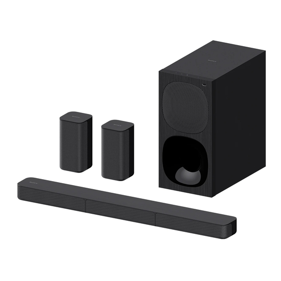
What's in the Box
List of included items with the HT-S20R system.
Servicing Notes
Unleaded Solder
Guidelines for using unleaded solder and its characteristics.
Fuse Replacement Note
Important safety precautions for replacing fuses.
Preparation for Operation Check
Requirements for confirming unit operation before servicing.
Discharge Processing Method
Procedure for safely discharging capacitors in the subwoofer.
Protection Feature
Explanation of the system's protection mode and troubleshooting.
Operation Check with Heatsink Removed
Precautions for operating the unit with the heatsink removed.
Reset Method
Steps to reset the system settings to their initial status.
Bluetooth Connection Method
Procedure to check Bluetooth connection after replacement.
Surround Speaker Repair
Information on replacing or repairing surround speakers.
Electrical Parts Replacement Note
Guidance on replacing electrical parts on boards.
Heat Radiation Compound
Instructions for applying compound for heat dissipation.
Disassembly
Disassembly Flow
Overall sequence for disassembling the HT-S20R unit.
AMP Block Disassembly
Step-by-step guide for removing the amplifier block.
Main Board Disassembly
Procedure for removing the main printed circuit board.
Power Board Disassembly
Steps to remove the power supply board.
BT Module Disassembly
Guide for detaching the Bluetooth module.
Front Panel Block-1 Disassembly
First part of front panel removal instructions.
Front Panel Block-2 Disassembly
Second part of front panel removal instructions.
USB Board, Display Board Disassembly
Procedure to remove USB and display boards.
Front Panel Assy, Touch Key Board Disassembly
Steps for removing front panel assembly and touch key board.
SPK Unit (Subwoofer), Wood Box Assy Disassembly
Guide for removing subwoofer speaker unit and wood box.
Speaker Block-1 Disassembly
First part of bar speaker block removal.
Speaker Block-2 Disassembly
Second part of bar speaker block removal.
Grille Assy_L Disassembly
Procedure for removing the left grille assembly.
Grille Assy_C Disassembly
Procedure for removing the center grille assembly.
Grille Assy_R Disassembly
Procedure for removing the right grille assembly.
SPK Unit (Bar Speaker) Disassembly
Steps to remove the bar speaker unit.
Rubber Foot, Cushion Foot, Rear Panel Block Disassembly
Instructions for removing feet and rear panel.
Troubleshooting
Starting Up Issues (SA-WS20R)
Diagnosing problems with system startup.
Touch Key Board Malfunction (SA-WS20R)
Troubleshooting the touch key board.
Audio Output Check (SA-WS20R)
Steps to check audio output functionality.
Diagrams
Block Diagram
Overall system block diagram.
Circuit Boards Location
Diagram showing the physical location of circuit boards.
Printed Wiring Board - Main Board (SA-WS20R)
Component layout for the main board.
Schematic Diagram - Main Board (1/2) (SA-WS20R)
Electrical schematic for the main board (part 1).
Schematic Diagram - Main Board (2/2) (SA-WS20R)
Electrical schematic for the main board (part 2).
Printed Wiring Board - USB Board (SA-WS20R)
Component layout for the USB board.
Schematic Diagram - USB Board (SA-WS20R)
Electrical schematic for the USB board.
Printed Wiring Board - Display Board (SA-WS20R)
Component layout for the display board.
Schematic Diagram - Display Board (SA-WS20R)
Electrical schematic for the display board.
Printed Wiring Board - Touch Key Board (SA-WS20R)
Component layout for the touch key board.
Schematic Diagram - Touch Key Board (SA-WS20R)
Electrical schematic for the touch key board.
Printed Wiring Board - Power Board (SA-WS20R)
Component layout for the power board.
Schematic Diagram - Power Board (SA-WS20R)
Electrical schematic for the power board.
IC Block Diagrams
General overview of IC block diagrams.
Main Board IC Block Diagram (IC500 TAS5538)
Detailed block diagram for IC500.
IC Block Diagram (IC501-503 TAS5614LA)
Detailed block diagram for IC501-503.
IC Pin Function Description
General overview of IC pin functions.
Main Board IC Pin Description (IC304 MT8307OQE)
Pin description for IC304 on the main board.
IC Pin Function Description (Continued)
Continuation of IC pin function descriptions.
Exploded Views
Subwoofer Front Section (SA-WS20R)
Exploded view of the subwoofer's front assembly.
Subwoofer AMP Section (SA-WS20R)
Exploded view of the subwoofer's amplifier section.
Bar Speaker Section (SS-S20R)
Exploded view of the bar speaker assembly.
Surround Speaker Section (SS-SS20R)
Exploded view of the surround speaker assembly.
Need help?
Do you have a question about the SS-SS20R and is the answer not in the manual?
Questions and answers