Table of Contents
Advertisement
Quick Links
CMT-Z100DiR/Z100iR
SERVICE MANUAL
Ver. 1.1 2009.11
• iPod is a trademark of Apple Inc., registered in the U.S. and
other countries.
• MPEG Layer-3 audio coding technology and patents licensed
from Fraunhofer IIS and Thomson.
• Windows Media is a registered trademark of Microsoft Corpo-
ration in the United States and/or other countries.
Amplifier section
European model:
DIN power output (rated):
16 + 16 watts (8 ohms at 1 kHz, DIN)
Continuous RMS power output
(reference):
20 + 20 watts (8 ohms at 1 kHz,
10% THD)
Music power output (reference):
20 + 20 watts (8 ohms at 1 kHz,
10% THD)
Latin American model:
DIN power output (rated):
16 + 16 watts (8 ohms at 1 kHz, DIN)
Continuous RMS power output
(reference):
20 + 20 watts (8 ohms at 1 kHz,
10% THD)
Inputs
AUDIO IN (stereo mini jack):
Voltage 0.8 V, impedance 47 kilohms
Outputs
PHONES (stereo mini jack):
accepts headphones with an
impedance of 8 ohms or more
USB section
Supported bit rate:
MP3 (MPEG 1 Audio Layer-3):
32
320 kbps, VBR
WMA: 48
192 kbps
AAC: 48
320 kbps
Sampling frequencies:
MP3 (MPEG 1 Audio Layer-3):
32/44.1/48 kHz
WMA: 44.1 kHz
AAC: 44.1 kHz
(USB) port:
Maximum current:
500 mA
Sony Corporation
9-889-528-02
2009K05-1
Audio&Video Business Group
©
2009.11
Published by Sony Techno Create Corporation
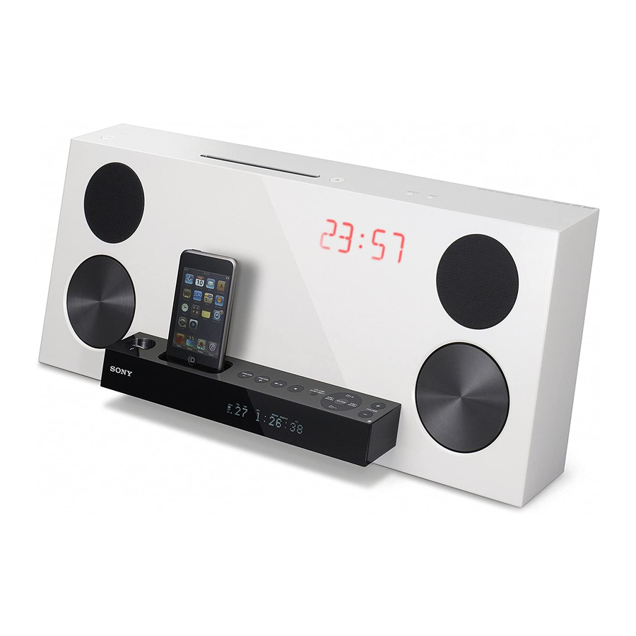
Photo: CMT-Z100iR
SPECIFICATIONS
CD player section
System:
Compact disc and digital audio
system
Laser Diode Properties
Emission Duration: Continuous
Laser Output*: Less than 1000μW
* This output is the value measurement
at a distance of 200mm from the
objective lens surface on the Optical
Pick-up Block with 7mm aperture.
Frequency response: 20 Hz
20 kHz
Signal-to-noise ratio: More than 90 dB
Dynamic range: More than 90 dB
Tuner section
DAB tuner section (CMT-Z100DiR only):
Frequency range*
Band-III:
239.200 (13F) MHz
174.928 (5A)
* For details, see "DAB frequency table"
(page 48).
Antenna: DAB lead antenna
Antenna terminal: 75 ohms, F female
Model Name Using Similar Mechanism
CD Mechanism Type
Optical Pick-up Block Name
DAB frequency table (Band-III)
Frequency
Label
Frequency
Label
174.928 MHz
5A
209.936 MHz
10A
176.640 MHz
5B
211.648 MHz
10B
178.352 MHz
5C
213.360 MHz
10C
180.064 MHz
5D
215.072 MHz
10D
181.936 MHz
6A
216.928 MHz
11A
183.648 MHz
6B
218.640 MHz
11B
185.360 MHz
6C
220.352 MHz
11C
187.072 MHz
6D
222.064 MHz
11D
188.928 MHz
7A
223.936 MHz
12A
190.640 MHz
7B
225.648 MHz
12B
192.352 MHz
7C
227.360 MHz
12C
194.064 MHz
7D
229.072 MHz
12D
195.936 MHz
8A
230.784 MHz
13A
197.648 MHz
8B
232.496 MHz
13B
199.360 MHz
8C
234.208 MHz
13C
201.072 MHz
8D
235.776 MHz
13D
202.928 MHz
9A
237.488 MHz
13E
204.640 MHz
9B
239.200 MHz
13F
206.352 MHz
9C
208.064 MHz
9D
* Frequencies are displayed to two decimal
places on this system.
FM stereo, FM/AM superheterodyne tuner
FM tuner section:
Tuning range:
87.5
108.0 MHz (50 kHz step)
Antenna: FM lead antenna
Intermediate frequency: 10.7 MHz
MICRO HI-FI SYSTEM
AEP Model
E Model
CMT-Z100iR
UK Model
CMT-Z100DiR
NEW
CDM86 ASSY
KHM-313CAB
AM tuner section:
Tuning range:
European model:
531
1,602 kHz (9 kHz step)
Latin American model:
530
1,710 kHz (10 kHz step)
531
1,710 kHz (9 kHz step)
Antenna: AM loop antenna
Intermediate frequency: 450 kHz
Speaker section
Speaker system:
2-way, bass-reflex type
Speaker units:
Woofer: 100 mm, flat type,
magnetically shielded
Tweeter: 20 mm, soft dome type
Rated impedance: 8 ohms
General
Power requirements:
European model: 220
240 V AC,
50/60 Hz
Latin American model: 120
127 or
220
240 V AC, 50/60 Hz, adjustable
with voltage selector
Power consumption: 30 watts
Dimensions (w/h/d):
Approx. 535 × 220 × 198 mm
Mass: Approx. 5.7 kg
Supplied accessories:
Remote Commander (1), R3 (Size
AAA) batteries (2), FM lead antenna
(1), AM loop antenna (1), DAB lead
antenna (1) (CMT-Z100DiR only)
Design and specifications are subject to
change without notice.
Advertisement
Table of Contents

Related Manuals for Sony CMT-Z100IR


Summarization of Contents
Specifications
Amplifier Section Specifications
Details on the amplifier's power output and performance.
CD Player Section Specifications
Specifications for the CD player, including laser properties and response.
Tuner Section Specifications
Technical specifications for the DAB and FM/AM tuner sections.
Speaker Section Specifications
Information on the speaker type, units, and impedance.
General Specifications
Overall product specifications like power requirements and dimensions.
Servicing Notes
Optical Pick-up and Laser Handling Precautions
Precautions for handling optical pick-up blocks and checking laser diode emissions.
Unleaded Solder Usage Guidelines
Guidance on using unleaded solder and its properties.
Disc Slot Lock Function Release
Procedure to release the disc slot lock for security.
Model Identification and IP Board Details
Information on model identification and IP board type differences.
Disassembly Procedures
Disassembly Flow and Panel Components
Outlines the overall disassembly sequence and panel component removal.
Back Panel and Board Component Removal
Procedures for removing back plates, DAB board, and chassis.
Main, CD, and Optical Drive Removal
Steps for removing main board, CD mechanism, and optical pick-up.
Display, Tuner, and Speaker Assembly Removal
Guidance for removing display, HP/tuner, and speaker assemblies.
Test Modes
Reset, Panel Test, and CD Modes
Covers cold reset, panel test, CD ship, and slot lock modes.
AM Tuning Interval and Touch Panel Settings
Allows AM tuning interval changes and touch panel beep configuration.
Electrical Checks
FM Tune Level Verification
Procedure for checking FM tuner sensitivity and tuning accuracy.
Diagrams and Schematics
Block Diagrams Overview
Block diagrams for CD, Tuner, Main, and Power Supply sections.
Printed Wiring Boards and Schematics - CD Section
Component layout and circuit schematics for the CD section.
Printed Wiring Boards and Schematics - DAB Section
Component layout and circuit schematics for the DAB section.
Printed Wiring Boards and Schematics - Main Section
Component layout and circuit schematics for the Main section.
Printed Wiring Boards and Schematics - Display Section
Component layout and circuit schematics for the Display section.
Printed Wiring Boards and Schematics - Sub Display Section
Component layout and circuit schematics for the Sub Display section.
Printed Wiring Boards and Schematics - Other Sections
Layouts and schematics for audio, key, and display power boards.
IC Block Diagrams
Illustrates the functionality of key integrated circuits.
Exploded Views
Rear and Front Panel Views
Exploded views of the rear cover and front panel sections.
Main, CD, and Display Assembly Views
Exploded views of main chassis, CD mechanism, and display assemblies.
Chassis and Speaker Component Views
Exploded views of the chassis, speaker boxes, and related components.
Electrical Parts List
DAB and Display Board Components
List of electrical components for the DAB and Display boards.
Main and DMB19C-32NUA Board Components
Electrical components for Main and DMB19C-32NUA boards.
Other Board Components
Electrical components for SW-VOLT, TOP KEY, and SUB DISPLAY boards.
Accessories
Included Accessories List
Lists accessories supplied with the main unit.
Revision History
Revision Log
Record of changes and updates made to the service manual.
Need help?
Do you have a question about the CMT-Z100IR and is the answer not in the manual?
Questions and answers