Table of Contents
Advertisement
Quick Links
Advertisement
Chapters
Table of Contents

Related Manuals for KOOLAIR SMLD Series


Summary of Contents for KOOLAIR SMLD Series
- Page 1 Fire protection www.koolair.com...
- Page 2 Fire protection Fire protection Rectangular and circular Circular terminal fire dampers fire damper Smoke extract louvre SCFR SCFC KOOLCOM fire damper Smoke extract dampers monitoring system CEVH SMLD SCDC GRAPHIC CONSOLE CONTENTS Rectangular and circular fire dampers BDK Circular terminal fire damper Intumescent louvres for air transfer SMLD Smoke extract dampers CEVH Smoke extract dampers...
-
Page 3: Table Of Contents
Fire protection Rectangular and circular fire dampers CONTENTS Description Declared performance Applications Model and dimensions Accessories Installation Operating Mechanisms Special finishes Technical data Coding... -
Page 4: Description
Fire protection Rectangular and circular fire dampers Description KOOLAIR rectangular fire dampers, models SCFR-PD, SCFR-GD, SFR3K1GT and circular fire dampers, models SCFC-PD and SCFC-GD, are approved in accordance with the Technical Building Code according to test standard UNE EN 1366-2 and classified according to EN 13501-3. - Page 5 Fire protection Circular fire dampers CE Marking Koolair fire dampers carry the CE marking in compliance with RPC-305/2011/EU, according to EN15650:2010. NF Marking The SCFR-PD, SCFR-GD, SCFC-PD and SCFC-GD models are certified under NF (NF264 Certification Standard, NF S 61-937-5 fire dampers).
-
Page 6: Declared Performance
Fire protection Declared performance The performance specifications of our range of fire dampers (rectangular and circular) are shown in the table below. Rectangular fire dampers Dimensions Construction Installation SCFR-PD Installation Classification (mm) details location CPR-2245-16 L: 200 → 800 d = 150 mm El-120 (ve i↔o) S Mortar Brick Wall... - Page 7 Fire protection Declared performance Circular fire dampers SCFC-PD Dimensions Construction Installation Installation Classification CPR-2244-16 (mm) details location d = 150 mm El-120 (ve i↔o) S Brick Ø: 100 → 355 Mortar ρ = 1900 kg/m³ (500 Pa) Wall d = 150 mm EI-180 (ho i↔o) S Floor slab Mortar...
-
Page 8: Applications
Fire protection Applications FIXED WALL EI-120 (v i↔o) S (RECTANGULAR) L (mm) 900 1000 1100 1200 1300 1400 1500 SCFR-PD SCFR-GD SCFR-GD STUD WALL EI-120 (v i↔o) S (RECTANGULAR) L (mm) SCFR-PD FIXED WALL EI-180 EI-180 (v i↔o) S (RECTANGULAR) L (mm) 900 1000 1100 1200 1300 1400 1500 SFR3K1GT... - Page 9 Fire protection Applications SLAB EI-120 (h i↔o) S / EI-180 (h i↔o) S (RECTANGULAR) L (mm) 900 1000 1100 1200 1300 1400 1500 SCFR-PD (EI-180-S) SCFR-GD (EI-120-S) STUD WALL EI-120 (v i↔o) S (CIRCULAR) Ø (mm) SCFC-PD FIXED WALL EI-120 (v i↔o) S / EI-180 (v i↔o) S (CIRCULAR) Ø...
-
Page 10: Model And Dimensions
Fire protection SCFR-PD Model and dimensions SCFR-PD fire dampers are available in standard sizes (duct size) with a length (L dimension) from 200 to 800 mm increasing in 50mm increments and a height (dimension H) from 100 to 600 mm increasing in 50mm increments. Drive shaft 1- Galvanised steel frame 2- Damper blade... - Page 11 Fire protection SCFR-GD Model and dimensions SCFR-GD fire dampers are available in standard sizes (duct size) with a length (L dimension) from 850 to 1500 mm increasing in 50mm increments and a height (dimension H) from 200 to 800 mm increasing in 50mm increments. Drive shaft 1- Galvanised steel frame 2- Damper blade 3- Mechanism/motor housing...
- Page 12 Fire protection SFR3K1GT Model and dimensions SFR3K1GT fire dampers are available in standard sizes (duct size) with a length (L dimension) from 200 to 1500 mm increasing in 50mm increments and a height (dimension H) from 200 to 800 mm increasing in 50mm increments. Drive axis 1- Galvanised steel frame 2- Blade...
- Page 13 Fire protection SCFC-PD Model and dimensions The standard dimensions (duct dimensions) of SCFC-PD fire dampers are: 100, 125, 160, 200, 250, 315 and 355 mm. Ø NOMINAL Drive shaft 1- Galvanised steel frame 2- Blade 3- Mechanism/motor housing 4- Intumescent seal 5- Fixing lug for installing in slab (optional)
- Page 14 Fire protection SCFC-GD Model and dimensions The standard dimensions (duct dimensions) of SCFC-GD fire dampers are: 400, 450, 500, 560, 630, 650, 700, 710, 750 and 800 mm. Ø NOMINAL Drive shaft 1- Galvanised steel frame 2- Damper blade 3- Mechanism/motor housing 4- Intumescent seal 5- Fixing lug for installing in slab (optional)
-
Page 15: Accessories
72 ºC (EN 10294) and its own signalling contacts (start and end of run). The servomotors are supplied for 24 V operation 230 V operation available on request. KOOLAIR incorporates motors from different manufacturers (Belimo, Siemens, etc.). SIEMENS BELIMO SERVOMOTOR (DAS) -
Page 16: Installation
Fire protection Installation Fire dampers are part of a building’s fire safety system and therefore special care must be taken with their installation. To install the dampers a perforation in the wall that is 100 mm greater than the nominal dimensions of the damper is required. - Page 17 Fire protection Installation Mounting in stud wall SCFR-PD SCFC-PD Wall studs must be offset Wall studs must be offset 48 mm 48 mm channels channels and uprights and uprights Pladur FOC 12.5 in 400 mm Pladur FOC 12.5 in 400 mm spacing spacing Screw PL 3.5x25...
- Page 18 Fire protection Installation Precautions during assembly The slot section of the damper frame must be sealed in when fitted both horizontally or vertically. There is an option to use fixing lugs fitted on the damper frame for installation in slab. In wall In stud wall In floor...
- Page 19 Fire protection Installation CORRECT INSTALLATION INCORRECT INSTALLATION Airflow direction is not critical i↔o) o (h i↔o) Manual Manual Manual device at 0º Manual device at top Manual device at 180º Manual device at bottom Motor-driven Motor-driven Motor-driven device at 0º Motor-driven device at top Motor-driven device at 180º...
- Page 20 Fire protection Installation CORRECT INSTALLATION INCORRECT INSTALLATION Airflow direction is not critical i↔o) o (h i↔o) Manual Manual Manual device at 0º Manual device at top Manual device at 180º Manual device at bottom Motor-driven Motor-driven Moto-driven device at 0º Motor-driven device at top Motor-driven device at 180º...
-
Page 21: Operating Mechanisms
Fire protection Operating mechanisms Operating mechanisms and electrical connections OPERATION BY MEANS OF TH-70 BIMETALIC FUSE OPERATION BY MEANS OF TH-70 BIMETALIC FUSE (MANUAL RESET) + COIL (MANUAL RESET) end (FC) and/or start of run (PC) switch end (FC) and/or start of run (PC) switch COIL - Closing (operating) of the damper when button “A”... - Page 22 Fire protection Operating mechanism Operating mechanisms and electrical connections OPERATION BY BIMETALLIC FUSE TH-70 + COIL + SERVOMOTOR WITH RETURN SPRING RESET MOTOR (AUTOMATIC RESET) (AUTOMATIC RESET) Connection box 1 Connection box 2 Connection Connection Connection box 1 Connection box 2 MOTOR end (FC) and/or start end (FC) and/or start...
- Page 23 Fire protection Activation Activation mechanisms and electrical connections SERVOMOTOR WITH RETURN SPRING SERVOMOTOR WITH RETURN SPRING + BSIA24-48 (SHUNT RELEASE) (AUTOMATIC + BSIA24-48 (UNDERVOLTAGE RELEASE) RESET) NF MARKING (AUTOMATIC RESET) NF MARKING - Damper is closed (operated) by providing an - Damper is closed (activated) by switching off the electrical supply (24 V AC or 24…48 V DC) to supply (24 V AC or 24…48 V DC) to terminals 3-4 of...
-
Page 24: Special Finishes
Fire protection Special finishes with duct connection spigots and truncated conical transformations Subject to checking with the Commercial Department, it is possible to supply rectangular and circular dampers with transformation spigots on request as a non-standard finish. These couplings may require a longer frame length than the defined standard in order to avoid the opening/closing of the blade from interfering with the spigot connections. -
Page 25: Technical Data
Fire protection Technical data SCFR-PD Table H \ L 0,015 0,019 0,023 0,026 0,030 0,034 0,038 0,041 0,045 0,049 0,053 0,056 0,060 0,53 0,50 0,47 0,45 0,42 0,39 0,37 0,35 0,32 0,30 0,28 0,26 0,25 dB(A) 0,025 0,031 0,038 0,044 0,050 0,056 0,063... - Page 26 Fire protection Technical data SCFR-PD Diagram 0,45 0,30 [dB(A)] 0,15 (m/s) 4500 1,00 3000 2000 1500 1000 0,10 0,01 (m/s) Selection example: For the given duct dimensions, we select a 600 x 500 mm SCFR-PD damper. We use the table on the previous page to find the following data: = 0,285 m = 0,14 = -1...
- Page 27 Fire protection Technical data SCFR-GD Table H \ L 0,120 0,150 0,180 0,210 0,240 0,270 0,300 0,330 0,360 0,390 0,420 0,450 0,480 0,84 0,75 0,69 0,63 0,58 0,53 0,49 0,45 0,42 0,39 0,36 0,34 0,31 dB(A) 0,130 0,163 0,195 0,228 0,260 0,293 0,325...
- Page 28 Fire protection Technical data SCFR-GD Table H \ L 1000 1050 1100 1150 1200 1250 1300 1350 1400 1450 1500 0,128 0,135 0,143 0,150 0,158 0,165 0,173 0,180 0,188 0,195 0,203 0,210 0,218 0,225 0,82 0,79 0,77 0,75 0,74 0,72 0,70 0,69 0,67...
- Page 29 Fire protection Technical data SCFR-GD Diagram 0,84 0,60 0,36 0,12 [dB(A)] (m/s) 1,00 1000 0,10 1500 2000 3000 (m/s) Selection example: For the given duct dimensions, we select a 1000 x 300 mm SCFR-GD damper. We use the table on the previous page to find the following data: = 0,25 m = 0,56 = -2...
- Page 30 Fire protection Technical data SFR3K1GT Table L \ H 0,024 0,033 0,042 0,051 0,060 0,068 0,077 0,086 0,095 0,104 0,112 0,121 0,130 0,84 0,75 0,68 0,64 0,60 0,57 0,54 0,52 0,50 0,49 0,47 0,46 0,45 dB(A) 0,038 0,052 0,066 0,079 0,093 0,107 0,121...
- Page 31 Fire protection Technical data SFR3K1GT Diagram 0,90 0,50 0,35 0,25 0,20 [dB(A)] 9 10 (m/s) Q (m 1,00 3000 2000 1000 0,10 0,01 (m/s)
- Page 32 Fire protection Technical data SCFC-PD Diagram [dB(A)] [m/s] 1000 10000 Q [m Selection example: For the given duct dimensions, we select a SCFC-PD damper with a diameter of 200 mm for a flow rate of 500 m Referring to the diagram above using this flow rate we find the following data: : 5,3 m/s.
- Page 33 Fire protection Technical data SCFC-GD Diagram 710 750 800 650 700 [m/s] [dB(A)] 1000 10000 100000 Q [m Selection example: For the given duct dimensions, we select a SCFC-GD damper with a diameter of 500 mm for a flow rate of 5000 m Referring to the diagram above using this flow rate we find the following data: : 8,1 m/s.
-
Page 34: Coding
Fire protection Coding Damper model (see table p. 5 declared performance) SCFR-PD SCFR-GD SFR3K1GT SCFC-PD SCFC-GD Activation. Components + TH-70 + B RUPT 24 V CC + FC/PC + MOTOR-24-RESET + TH-70 + FC + B RUPT 48 V CC + FC/PC + MOTOR-24/48-RESET + TH-70 + PC/FC + B RUPT 24 V AC + FC/PC + MOTOR-24/48-RESET + B IMP 24 V CC + FC... - Page 35 Fire protection Circular terminal fire damper CONTENTS Description Dimensions Installation Technical Data...
- Page 36 Fire protection Circular terminal fire damper Description Koolair’s BDK circular terminal fire dampers are approved with respect to RPC305, according to EN 15650 and according to testing standard UNE-EN 1366-2. They are installed in circular ventilation and air conditioning ductwork installations where the ductwork penetrates walls to prevent the propagation of fire.
- Page 37 Fire protection Dimensions NOMINAL ØGAP1 GAP2 200x200 225x225 250x250 260x260 280x280 300x300 Units in mm ØGap1 Fixed wall 1. Neck. Gap2 Stud wall 2. Blade. 3. Adhesive. 4. Intumescent seal. 5. Fusible link 72ºC. 6. Rubber seal. 7. Strip.
- Page 38 Fire protection BDK damper installation with direct connection to GPD extract louvre The BDK circular terminal fire damper can be installed in a fixed wall or a stud wall with a direct connection to a GPD extract louvre. The characteristics of both types of installation are shown below. Stud wall Fixed wall FIXED WALL...
- Page 39 Fire protection BDK damper installation with ductwork connection The BDK circular terminal fire damper can be installed in a fixed wall or a stud wall with a ductwork connection. The characteristics of both types of installation are shown below. Stud wall Fixed wall STUDWALL FIXED WALL...
- Page 40 Fire protection Technical data Quick selection tables Q (m [dB(A)] ΔP (Pa) (m/s) TAMAÑO Q (m /h): Flow rate. ∆P (Pa): Pressure loss. [dB(A)]: Sound power level. (m/s): Duct velocity. Selection chart [m/s] [dB(A)] 1000 Q [m...
- Page 41 Fire protection Intumescent air transfer grilles CONTENTS Description Dimensions...
- Page 42 Fire protection Intumescent air transfer grilles Description Koolair LV intumescent grilles are used to compartmentalise zones in the event of a fire or high temperature gases. The LV grilles contain an intumescent material that expands in the event of fire to seal the ventilation duct in accordance with BS 476: Part 20 and 22 and UNE-EN 1634-1:2000.
- Page 43 Fire protection Intumescent air transfer grilles Models Up to 60 minutes resistance to fire and high temperature gases. LVV40. EI30/EI60 rectangular PVC intumescent grille with straight blades. LVC40. EI30/EI60 circular PVC intumescent grille with straight blades. Up to 180 minutes resistance to fire and hot gases. LVH44.
- Page 44 Fire protection Intumescent air transfer grilles Dimensions LVV40: Length: 100 mm to 600 mm (in 25 mm increments) Height: 100 mm to 600 mm (in 25 mm increments) Thickness: 40 mm LVC40: Diameter: up to 600 mm Thickness: 40 mm LVH44: Length: 100 mm to 600 mm (in 25 mm increments)
- Page 45 Fire protection SMLD Smoke Evacuation Damper CONTENTS Description Dimensions Installation Electrical connections Technical data Coding...
-
Page 46: Description
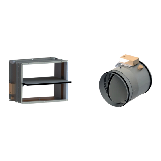
Fire protection SMLD Smoke Evacuation Damper Description Multi-blade smoke damper, suitable for use in low profile ductwork, approved in accordance with test standard UNE EN 1366-10 and classified according to EN 13501-4: EI 120 (ved i↔o) S 1500 AA multi. Designed according to EN 12101-8 specifications. - Page 47 The Koolair SMLD smoke evacuation damper, has CE marking, No. 0370-CPR-1688 in compliance with RPC-305/2011/EU, according to EN15650:2010. NF Marking The Koolair SMLD smoke evacuation damper, is certified to NF marking. (NF264 Certification Standard, NF S 61-937-10 smoke evacuation dampers). Regulations The SMLD damper is approved according to the European Test Standard UNE-EN 1366-10 and European classification standard UNE-EN 13501-4, where EI 120 (ved i↔o) S 1500 AA multi:...
-
Page 48: Dimensions
Fire protection SMLD Smoke Evacuation Damper Dimensions Damper Drawing Press to open the components’ Space for mechanism protective cover Product label Electrical connections Frame Blades Casing Fire resistance according to EN 13501 - 4 EI 120 (Ved - i o) S 1500 AA MULTI Dimensions and openings L Dimensions (see drawing) Nominal dimensions... - Page 49 Fire protection SMLD Smoke Evacuation Damper Dimensions Installation and commissioning SMLD Damper RPK Smoke extract grille Mounting frame Holes Ø 3 SMLD damper application in installations which employ ductwork different from that which has been submitted for certification testing: SMLD smoke control dampers, for use in multi-compartment systems (multi), are applicable in ducts that are tested in accordance with EN1366-8 as appropriate for each particular case or manufactured from materials with the same density or greater thickness than those used in the certification test.
-
Page 50: Installation
Fire protection SMLD Smoke Evacuation Damper Installation Use of mounting frame Ductwork UNE-EN 1366-8 Mounting frame Precautions: • Make sure the mounting frame is perpendicular before installation. • Fix the frame to the duct using the 4 screws provided with the frame. •... -
Page 51: Electrical Connections
Fire protection SMLD Smoke Evacuation Damper Connections Operating mechanism electrical connections FCU: safety position (end of run) one-pole contact. DCU: waiting position (start of run) one-pole contact. FCB: safety position (end of run) two-pole contact. DCB: waiting position (start of run) two-pole contact. Left Right •... - Page 52 Fire protection SMLD Smoke Evacuation Damper Connections • Operation and reset by electric servomotor (CE Marking): Supply voltage 24 V AC/DC (model BLE24) or 230 V AC (model BLE230). These motors integrate start of run (DCU) and end of run limit switches (FCU). The motor supply must be of SES (Safe Electrical Supply) type. A second start of run (DCB) and end of run limit switch (FCB) can be optionally included.
-
Page 53: Technical Data
Fire protection SMLD Smoke Evacuation Damper Technical Data SECTION THRouGH H OPERATING MECHANISM MOUNTING FRAME (OPTIONAL) CROSS SECTION THROUGH L Mounting frame Conducto s/norma UNE-EN1366-8 Blades Mounting frame Units in mm Free area table (dm Height Hn (mm) Blades (mm) 1000 11,0 12,2... - Page 54 Fire protection SMLD Smoke Evacuation Damper Technical Data SMLD Graph SMLD Vp-ΔP Key: damper air velocity in m/s. ΔP damper static pressure loss in Pa. Selection example: To calculate the static pressure loss across an SMLD damper for a given flow rate Q(m /h) the air velocity V (m/s) is calculated in relation to the damper air passage (dm...
-
Page 55: Coding
Fire protection SMLD Smoke Evacuation Damper Coding Damper dimensions and model SMLD – L x H (mm) Activation. Components + MOTOR-BLE24 + MOTOR-BLE230 + SHUNT REL 24 V DC + SoR/EoR LS + SHUNT REL 48 V DC + SoR/EoR LS + SHUNT REL 24 V AC + SoR/EoR LS + SHUNT REL 48 V AC + SoR/EoR LS + SHUNT REL 24 V DC + SoR/EoR LS + MOTOR RESET-BL24/48... - Page 56 Fire protection CEVH Smoke Evacuation Damper CONTENTS Description Dimensions Installation Assembly Electrical connections Technical data Coding...
-
Page 57: Description
Fire protection CEVH Smoke Evacuation Damper Description Smoke evacuation damper with 2-blade (2P), double door type swiveling closure, designed to be used for the supply of primary air and smoke evacuation in buildings with high levels of public footfall and in high-rise buildings. Approved in accordance with test standard UNE EN 1366-10 and classified according to EN 13501-4: EI120 (ved i↔o) S 1500 AA multi. - Page 58 The Koolair CEVH smoke evacuation damper, carries CE marking, no. 0370-CPR-1687 in compliance with RPC-305/2011/EU, according to EN15650:2010. NF Marking The Koolair CEVH smoke evacuation damper, is certified for NF marking. (NF264 Certification Standard, NF S 61-937-10 smoke evacuation dampers). Standard The CEVH damper is approved according to the European Test Standard UNE-EN 1366-10 and European classification standard UNE-EN 13501-4, where EI 120 (ved i↔o) S 1500 AA multi:...
-
Page 59: Dimensions
Fire protection CEVH Smoke Evacuation Damper Dimensions Damper Drawing Coil protection plate Dimensions and openings Nominal Exterior Nomin Exterio length length al height r height Ln (mm) Lt (mm) Hn (mm) Ht (mm) 1000 1029 1000 1029 1050 1079 1050 1079 1100 1129... -
Page 60: Installation
Fire protection CEVH Smoke Evacuation Damper Installation CEVH damper RPK grille Smoke extract duct Metal mounting frame * P = (Ln / 2) + 90 CEVH damper application in installations which employ ductwork different from that which has been submitted for certification testing: CEVH smoke control dampers, for use in multi-compartment systems (multi), are applicable in ducts that are tested in accordance with EN1366-8 as appropriate for each particular case or manufactured from materials with the same density or greater thickness than those used in the certification test. -
Page 61: Assembly
Fire protection CEVH Smoke Evacuation Damper Assembly Use of mounting frame Ductwork in accordance with UNE-EN Mounting frame 4 Screws Precautions: • Make sure the mounting frame is perpendicular before installation. • Fix the frame to the duct using the 4 screws provided with the frame. •... -
Page 62: Electrical Connections
Fire protection CEVH Smoke Evacuation Damper Connections Electrical connections Access to coil’s FCU: safety position (end of run) one-pole contact. electrical connections DCU: waiting position (start of run) one-pole contact. and start and end of FCB: safety position (end of run) two-pole contact. run switches DCB: waiting position (start of run) two-pole contact. -
Page 63: Technical Data
Fire protection CEVH Smoke Evacuation Damper Technical Data Free area table (dm Length Ln (in mm) 1000 1050 1100 9,24 10,76 12,28 13,80 15,3 16,8 18,4 19,9 21,4 22,9 24,4 26,0 27,5 29,0 30,5 10,76 12,53 14,30 16,07 17,8 19,6 21,4 23,2 24,9... - Page 64 Fire protection CEVH Smoke Evacuation Damper Technical Data CEVH Graph CEVH Vp-ΔP Key: damper air velocity in m/s. damper static pressure. ΔP loss in Pa. Selection example: To calculate the static pressure loss across a CEVH damper for a given flow rate Q(m /h) the air velocity V (m/s) is calculated in relation to the damper air passage (dm...
- Page 65 Fire protection CEVH Smoke Evacuation Damper Coding Damper dimensions and model CEVH – L x H (mm) Activation. Components + SHUNT RELEASE 24 V DC + ER/SR LS + SHUNT RELEASE 48 V DC + ER/SR LS + SHUNT RELEASE 24 V AC + ER/SR LS + SHUNT RELEASE 48 V AC + ER/SR LS Accessories MM (Metal mounting frame)
- Page 66 Fire protection RPK Cover grille for smoke dampers CONTENTS Description and dimensions Coding, mounting and technical data...
- Page 67 Two versions are currently available: Fixed central core and removable central core (with 2 fixing variations). Application For protection of Koolair smoke dampers types SMLD and CEVH. They can be used in both supply and extract applications. Grille comprises of an aluminium frame with curved aluminium blades.
-
Page 68: Coding
Fire protection Coding RPK: Protection grille with fixed central core. RPK - 1A: Protection grille with removable core (visible screws). RPK - 2A: Protection grille with removable core (hidden screws). RPK-X: Protection grille with folding core (hidden screws). RPK-P: Protection grille with fixed central core (hidden screws). RPK-S: Protection grille with fixed central core (visible screws). - Page 69 Fire protection Mounting and technical data RPK + CEVH Legend Blade depth Formulary Overall length = (Ln / 2) - 5 + 93 Overall height = Ln + 28 Duct internal length = Hn + 28 Duct internal height Lh = Ln + 10 Damper nominal length Hh = Hn + 10 Damper nominal height...
- Page 70 Fire protection Technical data CEVH + RPK AIR FLOW 8 m/s Length Ln (mm) 1000 1050 1100 4611 5187 5764 6340 6916 7493 8069 8645 9222 9798 10374 10951 11527 12104 12680 5187 5836 6484 7132 7781 8429 9078 9726 10374 11023 11671 12320 12968 13617 14265 5764 6484 7205...
- Page 71 Fire protection SCDC Smoke Evacuation Damper CONTENTS Description Connections Dimensions Selection chart Installation Coding...
-
Page 72: Description
- Areas of public gathering - ERP - Collective places - …. The SCDC smoke evacuation damper can be associated with KOOLAIR’s KOOLCOM management and monitoring system for fire dampers and other available models of smoke evacuation dampers. Declared smoke extraction performance... -
Page 73: Connections
Fire protection SCDC Smoke Evacuation Damper Connections Operating mechanism electrical connections FCU: safety position (end of run) one-pole contact. DCU: waiting position (start of run) one-pole contact. FCB: safety position (end of run) two-pole contact. DCB: waiting position (start of run) two-pole contact. - Manual reset, activated by electric coil (CE and NF marking). - Page 74 Fire protection SCDC Smoke Evacuation Damper Connections - Automatic activation and reset by servomotor (CE Marking): SCDC smoke extract dampers are activated and reset by means of a servomotor with a supply voltage of 24 V AC/DC (model BLE24) or 230 V AC (model BLE230). These motors include start and end of run limit switches to monitor the opening/closing status of the damper.
-
Page 75: Dimensions
Fire protection SCDC Smoke Evacuation Damper Dimensions NOMINAL H SCDC SMOKE DAMPER FREE AREA TABLE dm Length Ln (mm) 950 1000 1050 1100 1150 1200 10,7 11,5 12,2 13,0 13,8 14,6 15,3 16,1 16,9 17,7 18,4 10,0 11,1 12,1 13,1 14,1 15,2 16,2 17,2 18,2 19,3 20,3 21,3 22,3 23,4 24,4 11,2 12,5 13,8 15,0 16,3 17,6 18,9 20,1 21,4 22,7 24,0 25,2 26,5 27,8 29,1 30,3 10,4 11,9 13,4 14,9 16,5 18,0 19,5 21,0 22,6 24,1 25,6 27,1 28,7 30,2 31,7 33,2 34,8 36,3 10,3 12,1 13,8 15,6 17,4 19,2 20,9 22,7 24,5 26,3 28,0 29,8 31,6 33,4 35,1 36,9 38,7 40,5 42,2... -
Page 76: Selection Chart
Fire protection SCDC Smoke Evacuation Damper Selection Chart SCDC V -ΔP = damper air velocity in m/s. ΔP = static pressure loss across the damper in Pa. Selection example: To calculate the static pressure loss across a damper for a given flow rate Q(m /h) the air velocity V (m/s) is calculated in relation to the free area A... -
Page 77: Installation
Fire protection SCDC Smoke Evacuation Damper Installation The approval and the certification requirements for the installation of the damper are shown below. DUCT SCREW SPAX ABC Ø5.5X50 DAMPER BODY MIN 100 SCDC damper application in installations which employ ductwork different from that which has been submitted for certification testing: SCDC smoke control dampers, for use in multi-compartment systems (multi), are applicable in ducts that are tested in accordance with EN1366-8 as appropriate for each particular case or manufactured from materials with the same density or greater thickness than those used in the certification test. -
Page 78: Coding
Fire protection SCDC Smoke Evacuation Damper Coding Damper model (see table p. 5 Declared Performance) SCDC – L x H (mm) Activation. Components + MOTOR-BLE24 + MOTOR-BLE230 + SHUNT RELEASE 24 V DC + ER/SR LS + SHUNT RELEASE 48 V DC + ER/SR LS + SHUNT RELEASE 24 V AC + FC/PC + SHUNT RELEASE 48 V AC + FC/PC + SHUNT RELEASE 24 V DC + FC/PC + MOTOR RESET-BL24/48... - Page 79 Fire protection KOOLCOM fire damper monitoring system CONTENTS Description General system schematic diagram System components KHUK connection schematic diagram Accessories Coding Environment and guarantee...
-
Page 80: Description
Fire protection KOOLCOM fire damper monitoring system. Introduction KOOLCOM is an electronic control system for fire dampers that allows the condition and functionality of each fire damper to be periodically and automatically monitored and checked. It can also close the dampers should the fire alarm be activated. -
Page 81: General System Schematic Diagram
Fire protection General schematic diagram of the KOOLCOM monitoring system. Note: If the KHUK alarm input is connected to a fire panel, the modbus wiring between KHUK and DCUs, and between KHUK and the BMS, must be flame retardant. (Possible connections for 1 to 247 KHUKs). -
Page 82: System Components
They are integrated in the KOOLCOM fire damper control and supervision system. This system is completed with KHUK units (KoolCom Hub Unit KoolAir), which allow DCUs (1CH or 4CH) to be grouped in sets of 32 units, and connects the colour, touch screen consoles. - Page 83 Fire protection Specifications (DCU 1CH) • Maximum load on the damper motor output: 24V (AC/DC) model: 230V AC model: 0.5A • Maximum load in the detection zone: 100mA • Maximum power consumption (without detector or damper): 24V (AC/DC) model: 100mA@24V 230V AC model: 70mA@230V •...
- Page 84 Fire protection Damper Control Unit 1 channel (DCU 1CH) Input Binary ModBus ModBus 24 AC/DC Default load address termination values activation Direct Universal Smoke Connection Cable tie connection connection detector ModBus 230v Belimo / Siemens Input connector 230v AC The universal damper connection is a 5-wire connection: o Contacts: - S4+S1: can be connected inside the damper.
- Page 85 Fire protection Damper Control Unit 1 channel connection (DCU 1CH): two versions (24V / 230V) 100-DCK300 - 24V: Power 100-DCK400 - 230V: Power 220V ModBus IN KHUK ModBus OUT DCUs DETECTOR Contacts Motor Power supply 230V (cable tie is essential) or 24V. 2 wires. ModBus.
- Page 86 They are integrated in the KOOLCOM system for controlling and supervising motor-driven fire dampers and four smoke detectors (zones). This system is completed with KHUK units (KoolCom Hub Unit KoolAir), which allow DCUs to be grouped (1CH or 4CH) in sets of 32 units, in addition to connecting the colour, touch screen consoles.
- Page 87 Fire protection Specifications (DCU 4CH) • Maximum joint load on the damper motor outputs: 24V (AC/DC) model: 230V AC model: 0.5A • Maximum load in the detection zone: 100mA per zone / 300 mA combined • Maximum consumption (without detector or damper): 24V (AC/DC) model: 100mA@24V 230V AC model:...
- Page 88 Fire protection Damper Control Unit 4 channel (DCU 4CH) INPUT POWER 230V Model 230V AC ALR DAMPER DRY CONTACT OUTPUT activated in the event of an alarm FAN DAMPER DRY CONTACT OUTPUT supply, can be configured for extract MODBUS ADDRESS CONFIGURATION CONTACTS DAMPER 2...
- Page 89 Fire protection Damper Control Unit 1 channel connection (DCU 4CH): two models (24V / 230V) 100-DCK100 - 24V AC/DC: 100-DCK200 - 230V AC: Power Power 230V DAMPERS DAMPERS Contacts Contacts Motor Motor Contacts Contacts Motor Alarm input Motor Exterior ModBus ModBus OUT DCUs DETECTORS...
- Page 90 Fire protection System components. KHUK (HUB) The KHUK is a Modbus hub device that occupies a single address, allows up to 128 fire dampers and 128 smoke detectors (32 DCU-4CH units) to be managed. Each KHUK has: - 1 connection to the Koolcom console. - Direct connection to fire panel: •...
- Page 91 Fire protection System components. Graphic console The KOOLCOM graphic console allows monitoring and control of DCUs connected to the associated KHUK, facilitating the monitoring and control of fire dampers and smoke detectors (zones). The console allows information on the overall status of the system and each connected DCU to be displayed, as well as the basic parameters to be configured and managed.
-
Page 92: Khuk Connection Schematic Diagram
Fire protection KHUK connection schematic One KHUK has connections for up to 32 DCUs (maximum 128 dampers and 128 detectors), the wall mounted graphic console and a BMS. It can interact with the central fire alarm system with external alarms going to the KHUK and detected alarm coming from the KHUK. - Page 93 Fire protection KHUK AND DCUs Three wires with polarity that connect exclusively to the DCUs. The KHUK contains the MODBUS termination. By inserting the MBUS TERM bridge into the furthest DCU, the two necessary terminations are achieved. Different DCU models (DCU- 1CH and DCU-4CH) can be mixed in the same bus.
- Page 94 Fire protection KHUK and alarms CENTRAL N.O. Alarm CENTRAL Output FIRE ALARM FIRE ALARM C RELE ON RELE Reset KHUK alarm Power supply KHUK Alarm activation N.O. Alarm Relay Output: Volt-free contacts with a Fire Alarm and Reset Input: When the +24V from the maximum switching capacity of 8Amp, which are closed source is received at the alarm input, the KHUK considers when any DCU informs the KHUK of the occurrence of an...
-
Page 95: Accessories
Fire protection Accessories This section describes the accessories that may be necessary during installation. Cable MODBUS This depends on the specific conditions of each installation, especially the level of electrical noise in the zones which the wiring passes through, the distance to be covered and the chosen connection speed. -
Page 96: Coding
Fire protection Accessories Graphic console back box Non-standard back box for installations where the graphic console is to be flush mounted instead of surface mounted. Coding CODE DESCRIPTION 100-UCK000 KOOLCOM HUB 100-TCK000 KOOLCOM GRAPHIC DISPLAY 100-DCK500 DAMPER CONTROL UNIT KOOLCOM, 4 DAMPERS, 24V (AC/DC) 100-DCK600 DAMPER CONTROL UNIT KOOLCOM, 4 DAMPERS, 230V AC 100-DCK300... -
Page 97: Environment And Guarantee
Fire protection Environment, guarantee and safety. ENVIRONMENT Never dispose of this equipment together with household waste. Electrical and electronic products contain substances that can be harmful to the environment if not disposed of properly. The symbol of a crossed out rubbish bin indicates the special collection of electrical appliances, differing from other urban rubbish. - Page 98 Fire protection Fire and smoke dampers UL Approval FSD-B-U / FSD-A-U and FLD-S-U / FLD-S-UD CONTENTS Description FSD-B-U / FSD-A-U Construction details FSD-B-U / FSD-A-U Dimensions FSD-B-U / FSD-A-U Operation FSD-B-U / FSD-A-U Description FLD-S-U / FLD-S-UD Construction details FLD-S-U / FLD-S-UD Dimensions FLD-S-U / FLD-S-UD Operation FLD-S-U / FLD-S-UD Periodic inspection FLD-S-U / FLD-S-UD...
- Page 99 Fire protection FSD-B-U / FSD-A-U Fire and smoke dampers. UL Approval Description The FSD-B-U and FSD-A-U models are 3V type multi-blade fire and smoke dampers approved according to UL standards (UL555 and UL555S). Fire dampers close automatically to prevent fire and smoke from spreading to adjacent fire compartments through HVAC ventilation ductwork.
- Page 100 Fire protection FSD-B-U / FSD-A-U Fire and smoke dampers. UL Approval Construction details: Design and manufacture details FSD-B-U / FSD-A-U dampers Damper frame or casing material Galvanised steel Damper frame or casing thickness 1.6 mm Damper frame or casing profile type Omega profile –...
- Page 101 Fire protection FSD-B-U / FSD-A-U Fire and smoke dampers. UL Approval Dimensions: Dimensions Simple selection (L x H) Multiple selection (L x H) 152 x 203 mm (minimum dimension) 1828 x 1371 mm (maximum dimension) 914 x 1220 mm (maximum dimension) H / L 1000 1100...
- Page 102 Fire protection FSD-B-U / FSD-A-U Fire and smoke dampers. UL Approval Operation: The FSD-B-U and FSD-A-U models are designed to be fail-safe, allowing the dampers to automatically return to the desired position in the event of a fire and smoke. The damper operates (closes) if the power supply of 24 V (optionally 230 V) to the servomotor is interrupted, whether as a result of a system failure, a command from the control system or by the thermoelectric fusible link when the temperature exceeds 74º...
- Page 103 Fire protection Fire dampers with fusible link, FLD-S-U / FLD-S-UD. Approval UL Description The fire dampers are approved to withstand fire conditions for 90 minutes (1.5 hours) in accordance with UL555. They are 3V type multi-blade operated by the melting of a fusible link calibrated to 74º...
- Page 104 Fire protection Fire dampers with fusible link, FLD-S-U / FLD-S-UD. Approval UL Construction details: Construction details Damper frame or casing material Galvanised steel Damper frame or casing thickness 1.6 mm Damper frame or casing profile type Omega profile – 123 mm thick Closing blade material Galvanised steel Closing blade thickness...
- Page 105 Fire protection Fire dampers with fusible link, FLD-S-U / FLD-S-UD. Approval UL Operation: Complete with thermal fusible link set at 74ºC. They are designed to be fail-safe, allowing the dampers to close automatically when the temperature in the duct reaches the fuse design temperature..
- Page 106 Fire protection Fire dampers with fusible link, FLD-S-U / FLD-S-UD. Approval UL Periodic inspection, testing and maintenance The basic inspection, testing and maintenance procedures are described below. Inspection: Regular inspection, testing and maintenance are essential to ensure that the fire and smoke dampers in an installation operate as intended.
- Page 107 Fire protection Fire damper FSD-B-U / FSD-A-U FLD-S-U / FLD-S-UD. Technical data Selection chart FSD-B-U / FSD-A-U FLD-S-U / FLD-S-UD 1000 1,80 [dB(A)] 1,040 0,540 0,200 0,54 (m/s) 4500 4500 1,00 3000 3000 2000 2000 1500 1500 1000 1000 0,10 0,01 (m/s) Selection example:...
- Page 108 Fire protection Fire damper FSD-B-U / FSD-A-U FLD-S-U / FLD-S-UD. Technical data Table FSD-A-U / FSD-B-U/ FLD-S-U / FLD-S-UD L \ H 0,030 0,045 0,060 0,075 0,090 0,105 0,120 0,135 0,137 1,80 1,80 1,80 1,80 1,80 1,80 1,80 1,80 1,80 dB(A) 0,040 0,060...
- Page 109 Fire protection Fire dampers FSD-B-U / FSD-A-U FLD-S-U / FLD-S-UD. Technical data Table FSD-A-U / FSD-B-U H \ L 0,20 0,30 0,40 0,50 0,60 0,70 0,80 0,90 0,91 1000 1,80 0,99 0,74 0,54 0,37 0,25 0,20 0,20 0,20 dB(A) 0,22 0,33 0,44 0,55...
- Page 110 Fire protection Fire dampers FSD-B-U / FSD-A-U FLD-S-U / FLD-S-UD. Technical data Table FLD-S-U / FLD-S-UD L \ H 1000 1100 1200 1300 1400 1500 1600 1700 1800 1828 0,150 0,165 0,180 0,195 0,210 0,225 0,240 0,255 0,270 0,274 1,80 1,80 1,80 1,80...
- Page 111 Fire protection THIS CATALOG IS INTELLECTUAL PROPERTY. The partial or total reproduction of its contents is forbidden without the express and authoritative authorisation of KOOLAIR, S.A. CEN-PCI-1117-00...
- Page 112 KOOLAIR, S.A. Calle Urano, 26 Poligono industrial nº 2 – La Fuensanta 28936 Móstoles - Madrid - (España) Tel: +34 91 645 00 33 Fax: +34 91 645 69 62 e-mail: info@koolair.com www.koolair.com...
Need help?
Do you have a question about the SMLD Series and is the answer not in the manual?
Questions and answers