
Related Manuals for Vaisala GMW94RD


Summarization of Contents
General Information
About This Manual
Provides information for installing, operating, and maintaining GMW90 series transmitters.
Version Information
Details manual revisions, including changes and release dates.
Related Manuals
Lists other Vaisala manuals relevant to the GMW90 series.
Documentation Conventions
Explains how warnings, cautions, and notes are used in the manual.
Safety Precautions
Outlines crucial safety warnings and precautions for using the transmitter.
ESD Protection
Details measures to prevent damage from electrostatic discharge.
Recycling and Disposal
Provides guidance on proper material recycling and unit disposal.
Regulatory Compliances
Lists performance and environmental test standards the transmitters comply with.
Patent Notice
Lists patents protecting the GMW90 series and their national rights.
Trademarks
Identifies registered trademarks, including CARBOCAP®.
Software License
Explains the terms governing the use of software developed by Vaisala.
Warranty Information
Directs users to online resources for standard warranty terms and conditions.
Product Overview
Introduction to GMW90 Series
Introduces GMW90 series wall-mount transmitters for building automation.
GMW90 Series Transmitter Models
Lists and details differences between various GMW90 series transmitter models.
Output Parameters Explained
Describes the parameters supported by the GMW90 series, including units and definitions.
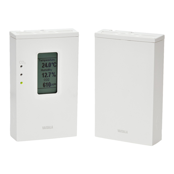
Transmitter Parts Identification
Identifies external and internal components of the GMW90 transmitter.
Decorative Cover Option
Details an installation accessory for customizing the transmitter's appearance.
Installation Guide
Configuration Before Installation
Explains configuration options for analog and digital output models before installation.
DIP Switch Settings for Analog Models
Details the function of DIP switches for configuring analog output models (GMW93/GMW94).
Changing DIP and Custom Configuration
Explains how changing DIP switch 8 affects configuration mode.
Configuration of Digital Output Models
Outlines configuration interfaces for digital output models (DIP switches, software).
DIP Switch Settings for Digital Models
Details DIP switch settings for digital output models (BACnet/Modbus).
Transmitter Addressing (BACnet/Modbus)
Explains how to set MAC addresses for BACnet and Modbus communication.
Selecting Transmitter Location
Provides guidance on choosing an optimal and representative installation location.
Installing the Mounting Base
Step-by-step instructions for securely installing the transmitter's mounting base.
Wiring GMW93R/RA
Recommended wiring diagrams for GMW93R/RA models.
Wiring GMW93
Wiring diagram for the GMW93 model, noting absence of humidity output.
Wiring GMW94R
Wiring diagram for the GMW94R model.
Wiring GMW94
Wiring diagram for the GMW94 model, noting absence of humidity output.
Wiring GMW95
Wiring diagram for the GMW95 model, including RS-485 connections.
Connecting Multiple Transmitters on RS-485
Instructions for connecting several transmitters on a single RS-485 line.
Common AC Power Supply Connection
Guidance on connecting a common AC power supply to multiple transmitters.
Transmitter Operation Guide
Display and Startup Screens
Explains the information shown on the transmitter's display during startup.
Measurement Screen Details
Describes the display of measured parameters and active indicators during normal operation.
Display Indicators Explained
Explains the meaning of various indicators shown on the transmitter display.
Service Port Connectivity
Details how to connect to the service port using a computer or MI70 indicator.
Connecting to a Computer
Instructions for connecting the transmitter to a computer via USB for configuration.
Installing USB Service Cable Driver
Steps for installing the necessary driver for the Vaisala USB service cable.
Terminal Application Settings (PuTTY)
Configuration settings for using a terminal application like PuTTY for serial communication.
List of Serial Commands
Comprehensive list of basic and advanced serial commands for transmitter control.
Transmitter Information Commands
Commands for retrieving transmitter model, firmware version, and serial number.
Transmitter Status Commands
Commands to view detailed transmitter status, including BACnet/Modbus information.
Show Measured Parameters Command
Command to list all measured and calculated parameters supported by the transmitter.
Setting Environmental Parameters
How to set ambient pressure for CO2 and humidity compensation using the ENV command.
Selecting Output Units (Metric/Non-metric)
Command to select display units (Celsius/Fahrenheit, etc.) for analog/digital outputs.
Analog Output Configuration
Explains analog output settings, mode, and error levels.
Set Analog Output Scaling
How to select output parameters and define scaling for analog channels.
Set Output Clipping and Error Limit
Defines behavior of analog outputs when measured values are outside the scaled range.
Select Display Parameters
Command to choose which parameters are displayed on the transmitter screen.
Serial Line Output Commands
Commands for controlling continuous output, single readings, and output intervals.
Set Output Interval Command
How to change the output interval for repeating measurement messages.
Set Output Format Command
Defines the message format for serial line output, including parameters and modifiers.
Serial Line Settings
Configuration of remote echo and serial line turnaround delay.
Calibration and Adjustment Commands
Overview of commands for calibrating and adjusting CO2, RH, and Temperature measurements.
Adjust CO2 Measurement
Commands for performing 1-point, 2-point adjustments, and clearing CO2 adjustments.
Adjust Humidity Measurement
Commands for performing 1-point, 2-point adjustments, and clearing RH adjustments.
Adjust Temperature Measurement
Commands for performing 1-point adjustments and clearing Temperature adjustments.
Enter Calibration and Adjustment Information
Commands to store text descriptions and dates for calibration/adjustment records.
Testing Analog Outputs
Command to force analog outputs to specific values and test their functionality.
Other Serial Commands
Commands for enabling advanced features, resetting the transmitter, and setting parameters.
Set BACnet Parameters
Commands for showing, setting, or reinitializing BACnet parameters.
Set CO2 Indicator LED Parameters
How to set limits for CO2 indicator LEDs or disable them.
Transmitter Maintenance
Cleaning Procedures
Instructions on how to clean the transmitter body and measurement modules.
Calibration and Adjustment Methods
Overview of methods for adjusting measurements using trimmers or service port.
Notes for CO2 Adjustment
Specific considerations for performing CO2 adjustments, including gas types and stabilization.
Effect of Pressure on CO2 Measurement
Details how ambient pressure impacts CO2 readings and compensation methods.
Adjustment Using Display and Trimmers
Step-by-step guide for performing adjustments using the transmitter's display and trimmers.
Adjustment Using a Hand-Held Meter
Instructions for adjusting the transmitter using Vaisala handheld meters (HM70, GM70).
Adjustment Using a Computer
Steps for performing adjustments via a computer using the Vaisala USB cable and terminal application.
Repair Maintenance
Information on replacing internal measurement modules if calibration fails.
Replacing the GM10 Module
Detailed procedure for replacing the CO2 measurement module (GM10).
Replacing the HTM10 Module
Detailed procedure for replacing the humidity and temperature module (HTM10).
Troubleshooting Guide
Problem Situations and Remedies
A table outlining common problems, their possible causes, and remedies.
Error Messages Explained
Lists error texts, IDs, possible causes, and suggested remedies for transmitter errors.
Viewing Active Error Messages
How to view currently active errors on the serial line using the ERRS command.
Viewing the Error Table
How to view the complete table of possible transmitter errors using the ERRT command.
Understanding Error States
Explains how critical or error-level issues affect analog output behavior.
Reverting to Factory Settings
Procedures to restore the transmitter to its original shipping configuration.
Factory Reset Using DIP Switches
Instructions for performing a factory reset using the transmitter's DIP switches.
Factory Reset Using Service Port
Instructions for performing a factory reset using the FRESTORE command via the service port.
Technical Support Contact
Information on how to contact Vaisala technical support for assistance.
Technical Specifications
Performance Specifications
Details measurement ranges, accuracy, and stability for CO2, Temperature, and Humidity.
Operating Environment Requirements
Specifies operating and storage temperature and humidity ranges, and compliance standards.
Inputs and Outputs
Lists available outputs (analog/digital), supply voltages, and power consumption.
Mechanics and Construction
Details physical properties like IP class, housing material, connectors, and weight.
Spare Parts and Accessories
Lists available spare parts, accessories, and their order codes.
Dimensional Drawings
Provides mechanical dimensions of the GMW90 series transmitter and mounting base.
BACnet Protocol Reference
BACnet Implementation Conformance Statement
Details vendor, product, software versions, and BACnet profile.
Standard Object Types Supported
Lists the standard BACnet object types supported by the device.
Data Link Layer Options
Specifies supported BACnet data link layers, including MS/TP master/slave.
Device Address Binding and Networking
Information on device address binding, networking options, and character sets.
Transmitter Models and BACnet Objects
Describes the BACnet objects available based on the transmitter model.
Device Object Properties
Detailed properties of the BACnet Device Object, including identifiers and status.
Carbon Dioxide Object Properties
Properties of the BACnet Carbon Dioxide Object, including units, status, and reliability.
Temperature Object Properties
Properties of the BACnet Temperature Object, including units, status, and reliability.
Relative Humidity Object Properties
Properties of the BACnet Relative Humidity Object, including units, status, and reliability.
Calculated Humidity Objects
Lists and describes calculated humidity objects like Dewpoint and Wet bulb temperature.
Operation Pressure Object Properties
Properties of the BACnet Operation Pressure Object used for CO2 compensation.
Operation Altitude Object Parameters
Parameters for the BACnet Operation Altitude Object linked to pressure compensation.
BACnet Smart Sensor BIBBs Supported
Lists the BACnet Interoperability Building Blocks (BIBBs) supported by the device.
BACnet Standard Application Services Supported
Lists which BACnet standard application services the device initiates or executes.
Modbus Protocol Reference
Modbus Functions Supported by GMW90
Lists the Modbus function codes supported by the GMW90 series transmitters.
GMW90 Modbus Measurement Data Registers
Details the Modbus registers for accessing measurement data, including units and multipliers.
GMW90 Modbus Status Registers
Information on Modbus registers for reading transmitter status and error codes.
GMW90 Modbus Configuration Parameter Registers
Details Modbus registers for configuring parameters like pressure and altitude.
GMW90 Modbus Device Identification
Lists Modbus registers for device identification, including vendor, version, and serial number.
GMW90 Modbus Exception Responses
Explains the exception codes returned by the transmitter for Modbus communication errors.
Need help?
Do you have a question about the GMW94RD and is the answer not in the manual?
Questions and answers