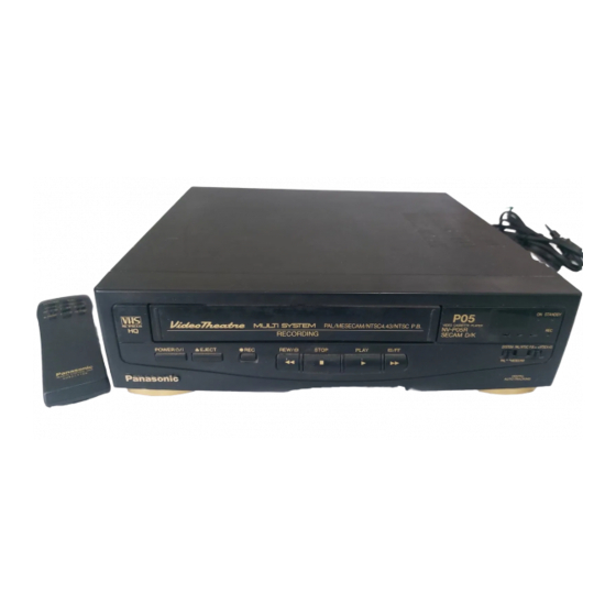
Advertisement
Quick Links
SPECIFICATIONS\ÒÅÕÍÈ×ÅÑÊÈÅ ÕÀÐÀÊÒÅÐÈÑÒÈÊÈ
SERVICE
INFORMATION\ÑÅÐÂÈÑÍÀß ÈÍÔÎÐÌÀÖÈß
ADJUSTMENT
PROCEDURES\ÌÅÒÎÄÈÊÀ ÍÀÑÒÐÎÉÊÈ
SYSTEM CONTROL & SERVO SECTION BLOCK
ÓÏÐÀÂËÅÍÈß È ÑÅÐÂÎÏÐÈÂÎÄÀ
LUMINANCE & CHROMINANCE SECTION BLOCK
ßÐÊÎÑÒÈ È ÖÂÅÒÍÎÑÒÈ
SCHEMATIC
DIAGRAM\ÏÐÈÍÖÈÏÈÀËÜÍÛÅ ÑÕÅÌÛ
Power schematic
System control & servo section in main schematic
ñèñòåìû óïðàâëåíèÿ è ñåðâîïðèâîäà (îñíîâíàÿ ïëàòà)
Luminance & chrominance section in main schematic
êàíàëîâ ÿðêîñòè è öâåòíîñòè (îñíîâíàÿ ïëàòà)
LED schematic
Head AMP schematic
Luminance & chrominance pack schematic
ÿðêîñòè è öâåòíîñòè (äîïîëíèòåëüíàÿ ïëàòà)
EXPLODED VIEWS & PARTS
Chassis parts section
Chassis parts section
Casing parts
section\êîðïóñ
Packing parts
ELECTRICAL REPLACEMENT PARTS
diagram\ïðèíöèïèàëüíàÿ ñõåìà èñòî÷íèêà ïèòàíèÿ
diagram\ïðèíöèïèàëüíàÿ ñõåìà èíäèêàòîðà
diagram\ïðèíöèïèàëüíàÿ ñõåìà óñèëèòåëÿ âèäåîãîëîâîê
LIST\ÑÁÎÐÎ×ÍÛÅ ×ÅÐÒÅÆÈ È ÑÏÈÑÎÊ ÇÀÏÀÑÍÛÕ ×ÀÑÒÅÉ
(1)\øàññè, ñåêöèÿ 1
(2)\øàññè, ñåêöèÿ 2
section\óïàêîâî÷íûå ìàòåðèàëû
LIST\ÑÏÈÑÎÊ ÝËÅÊÒÐÈ×ÅÑÊÈÕ ÇÀÏÀÑÍÛÕ ×ÀÑÒÅÉ
DIAGRAM\ÁËÎÊ-ÑÕÅÌÀ ÑÈÑÒÅÌÛ
DIAGRAM\ÁËÎÊ-ÑÕÅÌÀ ÊÀÍÀËÎÂ
diagram\ïðèíöèïèàëüíàÿ ñõåìà
diagram\ïðèíöèïèàëüíàÿ ñõåìà
diagram\ïðèíöèïèàëüíàÿ ñõåìà êàíàëîâ
Advertisement

Summarization of Contents
Service Information
Service Position
Details on how to position the mechanism for service and checks.
Checking of Gear Phase Alignment Condition
Procedure for checking the gear phase alignment condition of the mechanism.
Checking of Loading/Unloading Operation
Methods for checking the loading and unloading operation of the mechanism.
Checking of Reel Gears Operation
Procedure to check the operation of the reel gears.
UDD Cylinder Unit Replacement
Steps for replacing the UDD Cylinder Unit.
Adjustment Procedures
Test Equipment
Lists the required test equipment for electrical adjustments.
Preparation
Settings required during the adjustment procedures.
How to Read Adjustment Procedures
Guide on interpreting the format of adjustment procedures.
PG Shifter Adjustment
Procedure for adjusting the PG Shifter in the Servo Section.
Video EE Level Adjustment
Procedure for adjusting the Video EE Level in the Video Section.
White Clip Adjustment
Procedure for adjusting the White Clip Level.
Recording Current Adjustment
Procedure for adjusting the recording current.
Sync Tip Frequency Adjustment
Procedure for adjusting the sync tip frequency.
Deviation Adjustment
Procedure for adjusting the playback deviation level.
Schematic Diagrams
Power Schematic Diagram
Schematic diagram for the power supply circuit.
System Control & Servo Section in Main Schematic Diagram
Main schematic diagram for the system control and servo section.
Luminance & Chrominance Section in Main Schematic Diagram
Main schematic diagram for the luminance and chrominance section.
Head Amp Schematic Diagram
Schematic diagram for the head amplifier circuit.
Exploded Views & Parts List
Chassis Parts Section (1)
Exploded view and parts list for chassis components, section 1.
Chassis Parts Section (2)
Exploded view and parts list for chassis components, section 2.
Casing Parts Section
Exploded view and parts list for casing components.
Packing Parts Section
Exploded view and parts list for packing materials.


Need help?
Do you have a question about the NV-P05 REU and is the answer not in the manual?
Questions and answers