Table of Contents
Advertisement
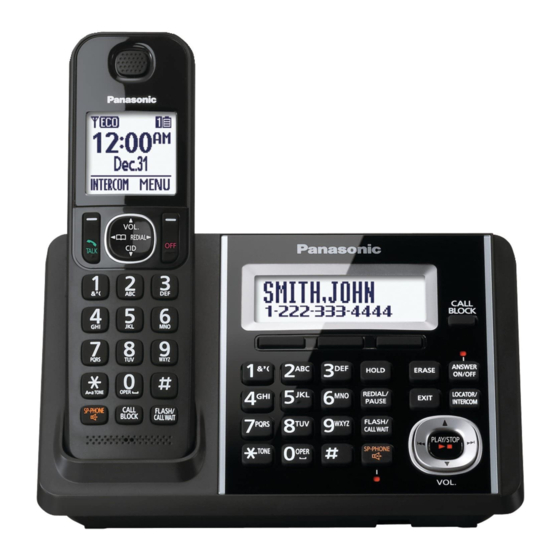
KX-TGFA30
(Handset)
KX-TGF370
(Base Unit)
Configuration for each model
Model No
Base Unit
KX-TGF340 1 (TGF340) 1 (TGFA30)
KX-TGF342 1 (TGF340) 2 (TGFA30)
KX-TGF343 1 (TGF340) 3 (TGFA30)
KX-TGF344 1 (TGF340) 4 (TGFA30)
KX-TGF345 1 (TGF340) 5 (TGFA30)
KX-TGF372 1 (TGF370) 2 (TGFA30)
KX-TGF373 1 (TGF370) 3 (TGFA30)
KX-TGF374 1 (TGF370) 4 (TGFA30)
KX-TGF375 1 (TGF370) 5 (TGFA30)
KX-TG585
1 (TGF370) 5 (TGFA30)
KX-TGFA30*
1 (TGFA30)
*KX-TGFA30 is also an optional accessory, which contains a
handset and a charger.
KX-TGF340
(Base Unit)
(Charger Unit)
Handset
Charger Unit Expandable
Up to 6
1
Up to 6
2
Up to 6
3
Up to 6
4
Up to 6
1
Up to 6
2
Up to 6
3
Up to 6
4
Up to 6
4
Up to 6
1
Telephone Equipment
KX-TGF340B
Model No.
KX-TGF342B
KX-TGF343B
KX-TGF344B
KX-TGF345B
KX-TGF372S
KX-TGF373S
KX-TGF374S
KX-TGF375S
KX-TG585SK
KX-TGFA30B
KX-TGFA30S
KX-TGFA30M
Digital Cordless Answering System
Link-to-Cell Bluetooth Convergence
Solution
Black
B:
Vesion
S: Silver Version
M: Metallic Black
(for U.S.A.)
© Panasonic System Networks Co., Ltd. 2015
Unauthorized copying and distribution is a violation
of law.
ORDER NO.: KM41501897CE
F13
Advertisement
Table of Contents

Summarization of Contents
Safety Precautions
For Service Technicians
Guidelines for service technicians to prevent hazards during repair.
Battery Caution
Risk of explosion if battery is replaced with an incorrect type.
About Lead Free Solder (PbF: Pb free)
Information on using lead-free solder for service and repair work.
Technical Descriptions
Circuit Configuration of TGF34x/TGF37x Series Phones
Overview of the product's circuit architecture and components.
US-DECT Description
Technical details on the US-DECT standard and its implementation.
Block Diagram (Base Unit_Main)
Visual representation of the main base unit's functional blocks and connections.
Circuit Operation (Base Unit)
Explanation of the operational principles and functions of the base unit's circuitry.
Block Diagram (Handset)
Visual representation of the handset's functional blocks and connections.
Circuit Operation (Handset)
Explanation of the operational principles and functions of the handset's circuitry.
Signal Route
Traces the path of signals through various components and connections.
Test Mode
Engineering Mode
Accessing and operating the device in engineering mode for advanced testing.
Service Mode
How to Clear User Setting (Handset Only)
Resets user settings on the handset to factory defaults.
Troubleshooting Guide
Troubleshooting Flowchart
Step-by-step diagnostic process to identify and fix problems.
Check Power
Steps to verify power supply and voltage levels for troubleshooting.
Check Link
Steps to troubleshoot connection issues between the handset and base unit.
Check the RF part
Diagnostic steps for identifying and resolving issues with the radio frequency components.
Registering a Handset to the Base Unit
Instructions for pairing a new handset with the base unit.
Check Caller ID
Troubleshooting steps for issues related to Caller ID functionality.
Check BT Communication
Steps to troubleshoot Bluetooth connectivity and data transfer issues.
Disassembly and Assembly Instructions
Disassembly Instructions
Step-by-step instructions for disassembling the product's main units.
How to Replace the Base unit LCD
Detailed procedure for replacing the liquid crystal display on the base unit.
How to Replace the Handset LCD
Detailed procedure for replacing the liquid crystal display on the handset.
Measurements and Adjustments
Equipment Required
Lists the necessary tools and equipment for measurements and adjustments.
The Setting Method of JIG
Instructions for setting up and connecting the JIG for measurements and adjustments.
Things to Do after Replacing IC or X'tal
Post-replacement procedures, including data download and adjustment.
Miscellaneous
How to Replace the Flat Package IC
Detailed steps for replacing Flat Package ICs on the circuit board.
Terminal Guide of the ICs, Transistors and Diodes
Identifies the function of pins and terminals for various electronic components.
Schematic Diagram
Schematic Diagram (Base Unit_Main)
Circuit diagram for the main components and functions of the base unit.
Schematic Diagram (Handset_Main)
Circuit diagram for the main components and functions of the handset.
Printed Circuit Board
Circuit Board (Base Unit_Main)
Component layout diagram for the main base unit's printed circuit board.
Bottom View (Base Unit_Main)
Shows the component layout on the reverse side of the base unit's main circuit board.
Circuit Board (Handset_Main)
Component layout diagram for the handset's main printed circuit board.
Bottom View (Handset_Main)
Shows the component layout on the reverse side of the handset's main circuit board.
Exploded View and Replacement Parts List
Cabinet and Electrical Parts (Base Unit)
Exploded view and list of cabinet and electrical components for the base unit.
Cabinet and Electrical Parts (Handset)
Exploded view and list of cabinet and electrical components for the handset.
Replacement Parts List
Comprehensive list of all replaceable parts with their part numbers and descriptions.
Fixtures and Tools
Lists necessary fixtures and tools for assembly, repair, and setup.


Need help?
Do you have a question about the KX-TGF343B and is the answer not in the manual?
Questions and answers