
Related Manuals for REA JET HR pro 4K


Summarization of Contents
Introduction and Key Features
System Overview
Describes the REA JET HR pro 2K/4K marking system and its underlying technology.
Key Characteristics
Highlights the main features and advantages of the REA JET HR pro series.
Modular Concept and Versatility
Details the modular design, accessory program, and versatile power supply capabilities.
Font and Charset Support
Explains the system's support for True Type Fonts and Unicode charsets.
About This Instruction Manual
Symbols Used in This Manual
Explains the meaning of safety and information symbols used throughout the manual.
Additional Safety Symbols
Details symbols for electrical hazards, vapors, fire, disposal, and personal protective equipment.
Safety Instructions and Handling
General Safety Instructions
Specifies requirements for commissioning, operation, and maintenance by trained personnel.
Handling Precautions
Advises on reading the manual, personnel qualification, and observing relevant regulations.
Responsibilities
Operator Responsibilities
Outlines operator obligations regarding personnel training and manual comprehension.
Employee Responsibilities
Defines employee obligations for work safety and adherence to manual instructions.
Intended Use and Misuse
Intended Use Guidelines
Defines the proper application of the REA JET HR pro 2K/4K for marking and labeling.
Expected Misuse Scenarios
Warns against improper uses such as pointing print heads at people or animals.
Hazards and Malfunctions
Handling Hazards
Discusses potential dangers to life, health, and assets from system use.
Malfunction Remediation
Details immediate shutdown and repair procedures for safety-impairing malfunctions.
Regulatory Information
EU Directives and CE Marking
Explains the purpose of EU directives, CE marking, Machinery, EMC, and Low-Voltage Directives.
Declarations of Conformity
Declaration of Conformity REA JET HRpro 2K
Official declaration that the REA JET HRpro 2K complies with relevant EU directives.
Declaration of Conformity REA JET HRpro 4K
Official declaration that the REA JET HRpro 4K complies with relevant EU directives.
Specific Hazards
Electrical and Fire Hazards
Warns about electrical hazards and prohibits open fire/heat near ink products.
Ink Handling Hazards
Details risks associated with ink, including skin/eye irritation and material safety data sheets.
Solvent Vapors and Personal Protective Equipment
Addresses risks from solvent vapors and mandates protective eyewear and gloves.
Additional Hazard Information
Disposal of Resources
Guides on proper disposal of operating resources according to safety data sheets and regulations.
Further Hazard Sources
Notes that this section is omitted.
Scope of Delivery, Transport, and Handling
Scope of Delivery Details
Refers to delivery details being available separately.
Transport Conditions
Specifies environmental conditions and handling precautions during transport.
Handling and Damages
Covers receiving inspection, procedures for damaged deliveries, and packaging for returns.
Unpacking and Packaging Disposal
Provides instructions for safe unpacking and proper disposal of packaging materials.
Mechanical Data, Assembly, and Installation
Mechanical Data Overview
Introduces the chapter detailing mechanical data and dimensions for optimal handling and assembly.
Control Device Mechanical Data
Dimensions for Cabinet Installation (REA JET HR pro 2K)
Presents mechanical dimensions and specifications for cabinet mounting of the 2K control device.
Dimensions for 19-inch System Installation
Details mechanical dimensions for installing the REA JET HR pro 2K control device in a 19-inch rack.
Dimensions for Use Without Cabinet
Shows mechanical data for installing the REA JET HR pro 2K control device without a cabinet.
Control Device Mechanical Data (HR pro 4K)
Dimensions for Cabinet Installation (REA JET HR pro 4K)
Provides mechanical dimensions for cabinet mounting of the REA JET HR pro 4K control device.
Dimensions for 19-inch System Installation (REA JET HR pro 4K)
Details mechanical dimensions for 19-inch rack mounting of the REA JET HR pro 4K control device.
Dimensions for Use Without Cabinet (REA JET HR pro 4K)
Shows mechanical data for installing the REA JET HR pro 4K control device without a cabinet.
Print Head Mechanical Data
Single Print Head Data
Presents mechanical dimensions and data for a single REA JET HR print head.
Double Print Head Data
Shows mechanical dimensions and data for a double REA JET HR print head.
Print Head Mounting Components
Print Head Retainer Rod Data
Details the mechanical data for the print head retainer rod.
Retainer Rod Data for Double Print Head
Presents mechanical data for a retainer rod used with a double print head.
Positioning and Alignment Components
Parallel Program Mechanical Data
Provides mechanical data and dimensions for the REA JET parallel program.
Measurement and Encoding Components
Shaft Encoder with Integrated Cable Data
Details the mechanical data for the shaft encoder with an integrated cable.
Suspended Measuring Arm Data
Shows mechanical data for the suspended measuring arm for shaft encoders.
HD Mount for Shaft Encoder Data
Presents mechanical data for the Heavy Duty mount for shaft encoders.
Signaling Components
Signal Lamp with Foot/Magnetic Foot Data
Details mechanical data for signal lamps with assembly foot and magnetic foot.
Signal Lamp with Assembly Bracket Data
Shows mechanical data for signal lamps with an assembly bracket.
Interface and I/O Components
I/O Connecting Element Data
Presents mechanical data and mounting dimensions for the I/O connecting element.
Assembly and Installation Procedures
Assembly and Installation Overview
Introduces the chapter detailing assembly and installation procedures for the system components.
Control Device Assembly
Control Device Assembly Points
Lists key considerations for assembling the control device, including stability and usability.
Control Device Installation Methods
Cabinet Installation
Explains how to install the control device in a cabinet using a DIN 35 mm supporting rail.
35 mm Supporting Rail Installation
Details the steps for mounting the control device onto a 35 mm supporting rail.
19-inch System Installation
Describes installing the control device using mounting brackets for 19-inch systems.
Direct Assembly Methods
Explains how to directly mount the control device to a machine or system using an assembly plate.
Additional Mounting Options
Covers mounting the joint clamp and installing the cover sheet with filter kit.
Print Head Assembly
Print Head Assembly Overview
Introduces the assembly of print heads and lists their benefits and capabilities.
Stripper Plate Assembly and Features
Stripper Plate Design and Function
Details stripper plate features like scope of delivery, product guidance, and protective milled edge.
Stripper Plate Mounting Features
Explains openings for sensors, symmetric design, guide wheels, and ground bolts on the stripper plate.
Ink Discharge and Screw Connections
Describes the ink discharge channel and screw connections on the stripper plate.
Print Head Installation with Stripper Plates
Single Stripper Plate Installation
Details the process of installing a print head with a single stripper plate.
Double Offset Stripper Plate Installation
Explains installing print heads with double offset stripper plates for increased print height.
Double Stripper Plate Fastening Points
Illustrates fastening points for the double stripper plate on the print head.
Linear Stripper Plate Installation
Describes installing print heads with double linear stripper plates for a 12.7 mm max. print height.
Linear Stripper Plate Assembly Details
Details assembly positions and screws for connecting two print heads with linear stripper plates.
Special Stripper Plate Options
Shortened Outlet Stripper Plate (87 mm)
Details the stripper plate with a shortened outlet (87mm) suitable for narrow spaces.
Shortened Outlet/Inlet Stripper Plate (51 mm)
Describes the stripper plate with shortened outlet and inlet (51mm) for extreme narrow spaces.
Positioning Wheel Option
Positioning Wheel Installation
Explains how to install an optional positioning wheel for product guidance.
Positioning Wheel Usage Considerations
Provides points to consider when using the positioning wheel for product alignment.
Product Sensor Installation
Product Sensor Mounting
Describes how to mount a product sensor directly onto the print head using a fastening bracket.
Product Sensor Assembly Methods
Standard Assembly Bracket Sensor Installation
Details sensor assembly using the standard bracket and screw types.
Sensor Mounting Steps
Outlines the step-by-step process for fastening the sensor and its cable.
Adapter Plate Sensor Installation
Explains sensor installation using an adapter plate for limited assembly spaces.
Adapter Plate Mounting Steps
Details the steps for installing a sensor using the adapter plate, including sensor distance changes.
Product Sensor Types and Data
Product Sensor Type 1 (E3Z-D81 J0SRW)
Provides details, application areas, and technical data for product sensor type 1.
Setting Product Sensor Type 1
Guides on setting the operating mode, sensitivity, and output function for sensor type 1.
Product Sensor Type 1 Sensitivity Adjustment
Details the step-by-step process for adjusting sensitivity for product sensor type 1.
Finalizing Product Sensor Type 1 Settings
Covers final sensitivity settings and notes for proper functionality of sensor type 1.
Product Sensor Type 2 (E3Z-LL81)
Details sensor type 2, its application areas, and technical data, including laser safety.
Setting Product Sensor Type 2
Guides on setting operating mode, scanning range, and output function for sensor type 2.
Product Sensor Type 2 Scanning Range Adjustment
Details the step-by-step process for adjusting the scanning range for product sensor type 2.
Finalizing Product Sensor Type 2 Settings
Provides notes for proper functionality and troubleshooting for sensor type 2.
Safety Instructions for Laser Sensor Type 2
Outlines safety precautions related to the laser beam of product sensor type 2.
Product Sensor Type 3 (E3ZM-V81)
Details sensor type 3, its application areas, and technical data, including RGB signal processing.
Setting Product Sensor Type 3
Guides on setting the sensor type 3 using the teach button for print mark and background.
Product Sensor Type 3 Teach-in Process
Details the step-by-step teach-in process for print mark and background for sensor type 3.
Print Head Assembly Sequences
Exploded View and Assembly Steps
Shows an exploded view and outlines the sequence for assembling a double print head.
Component List for Double Print Head Assembly
Lists the article numbers and descriptions for components in the exploded view.
Print Head Mounting with Retainer Rod
Retainer Rod Scope of Delivery and Use
Details the scope of delivery and application of HR retainer rods for print heads.
Proper Centering Element Installation
Emphasizes correct installation of the centering element for retainer rods to prevent damage.
Centering Element Details
Explains the centering element's role and procurement as an accessory.
Print Head Mounting Variations
Print Head Assembly with Retainer Rod
Shows assembly compilation and preferred mounting side for a print head with a retainer rod.
Retainer Rod Assembly Position Examples
Illustrates various assembly positions for the retainer rod with a print head.
Two Print Heads on Retainer Rod Assembly
Discusses assembling two print heads on a retainer rod and the use of group holders.
Group Holder for Print Head Assemblies
Shows installation of a group holder for two print heads and views of the assembly.
Parallelogram for Automatic Adjustment
Parallelogram Installation and Use Cases
Explains parallelogram use for automatic distance adjustment with examples of necessary applications.
Parallelogram Mounting and Requirements
Details parallelogram mounting considerations for side and top printing and spring assemblies.
Parallelogram Spring Preload and Setting Options
Describes setting spring preload and options for printing from top or side.
Parallelogram Assembly Examples
Shows arrangement and assembly examples for printing from the top with four print heads.
Shaft Encoder Installation
Shaft Encoder Overview and Technology
Introduces shaft encoders, their function, technology, and potential for damage from improper use.
Shaft Encoder Models
DG 5000 with Integrated Cable Data
Details the shaft encoder DG 5000 with integrated cable, its features, and suitability for small spaces.
Shaft Encoder Limit Values and Installation Points
Shaft Encoder Limit Values and Installation Points
Lists mechanical limit values and crucial installation points for solid shaft encoders.
Shaft Encoder with Hollow Shaft Data
Shaft Encoder with Hollow Shaft Data
Provides mechanical limit values and installation considerations for hollow shaft encoders.
Measurement Wheel Components
Measurement Wheels Technical Data
Details the technical data for three types of measuring wheels used with shaft encoders.
Measuring Wheel Usage Precautions
Advises on correct installation and potential assembly issues when using measuring wheels.
Measuring Arm Systems
Suspended Measuring Arm Benefits and Settings
Highlights benefits of the suspended measuring arm and explains contact pressure setting methods.
Heavy Duty Mounting Solutions
HD Mount for Encoder Benefits
Lists the advantages of the HD mount, particularly for rough environments.
HD Mount Synchronizing Disks and Limit Values
Details synchronizing disks for ratio adjustment and mechanical limit values for the HD mount.
Press-on Element for Shaft Encoders
Press-on Element Description and Benefits
Describes the press-on element as a cost-effective assembly device for solid shaft encoders.
Signal Lamp Installation
Signal Lamp Types and Features
Introduces REA JET signal lamps, their variants, and installation advantages.
I/O Connection Cable Installation
I/O Connection Cable Assembly and Disassembly
Details the installation and removal process for the I/O connection cable on a DIN rail.
I/O Multiplier Installation
I/O Multiplier Mounting Options
Explains installation of the I/O multiplier on a supporting rail or via direct fixation.
I/O Multiplier Direct Fixation Assembly
Details the steps for direct fixation assembly of the I/O multiplier, including housing and plate removal.
Shaft Encoder Multiplier Installation
Shaft Encoder Multiplier Mounting Options
Describes installation of the shaft encoder multiplier on a supporting rail or via direct fixation.
Shaft Encoder Multiplier Direct Fixation Assembly
Details direct fixation assembly steps for the shaft encoder multiplier, including housing and plate removal.
Electrical Connections to Control Device
Connection Overview
Lists the chapters detailing electrical connections and their descriptions.
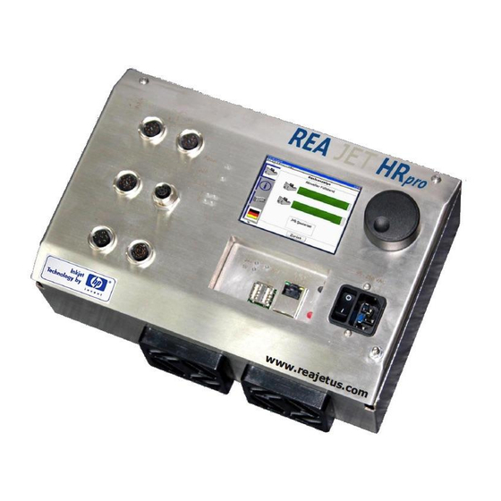
Control Device Connection Views
Shows visual representations of the REA JET HR pro 2K and 4K with labeled connections and elements.
Connection Descriptions
Connection Setup and Functionality
Provides a brief description of each connection setup and its primary function for both models.
HR pro 4K Specific Connections
Lists additional connections available specifically for the REA JET HR pro 4K model.
Detailed Connection Descriptions and Values
Mains Connection (A1) Details
Describes the mains connection, its assignment, and power supply values for the control device.
Ground Bolts and Ethernet Connection
Details ground bolt connections and the Ethernet port for network communication.
USB and Bulk System Connections
Explains USB connections for storage and the intended use of bulk system connections.
Bulk System Connection Details (A11)
Provides assignment and electrical limit values for the bulk system connection (A11).
Serial Connection Support Status
States that serial connections are not currently supported and depend on firmware version.
Encoder and Serial Connections
Explains connecting shaft encoders and observes supply voltage and interface types.
Shaft Encoder Connection Assignment (A7, A13)
Provides the pin assignment for shaft encoder connections (A7, A13).
Shaft Encoder Electrical Values and Circuit Diagram
Details electrical limit values and functional circuit diagrams for shaft encoder connections.
Digital Input/Output Connections
Digital I/O Connection (A8, A14)
Describes the digital input/output connections (A8, A14) and their galvanic separation.
I/O Connection Pin Assignment (A8, A14)
Shows the pin assignment for the I/O connection cable and connector for A8 and A14.
Digital I/O Electrical Values and Circuit Diagrams
Provides electrical limit values and functional circuit diagrams for digital inputs/outputs.
Digital I/O Circuit Diagrams and Functions
Presents circuit diagrams for digital outputs and notes on assigning functions to I/O.
Print Head Connections
Print Head Cable Connection Safety
Warns that print head cables can only be connected/disconnected when the device is deactivated.
Print Head Connection Assignment (A9-A16)
Details the pin assignment for all print head connections (A9, A10, A15, A16).
Control Device Installation and Mains Connection
Covers installation of the control device and specific safety warnings for mains connection.
Print Head Installation
Mentions the cold device cable and safety warnings for print head cable connections.
Print Head Connection Pin Assignment
Provides detailed pin assignment for print head connections, including wire colors.
REA JET Print Head Cable Specifications
Discusses print head cable lettering, carriers, and safety warnings during connection.
Stripper Plate and Product Sensor Installation
Stripper Plate Earthing and Sensor Connection
Covers earthing on the stripper plate and product sensor connection to the print head.
Product Sensor Electrical Values and Diagrams
Details electrical limit values, circuit diagrams, and measurements for the product sensor connection.
Sensor Plug Assembly and Alternative Input Connection
Explains sensor plug assembly and using digital inputs for alternative print triggering.
Sensor Connection to Digital Input
Sensor Connection Assignment for Digital Input 3
Details the sensor connection assignment for digital input 3, including pinouts and cable views.
Shaft Encoder Installation and Connectors
Shaft Encoder Plug Connector Details
Covers delivery scope and dimensions for shaft encoder plug connectors.
Shaft Encoder with M23 Connector Data
Provides pin assignment, electrical limit values, and pulse diagrams for M23 connector shaft encoders.
Shaft Encoder with Integrated Cable and M12 Plug
Details shaft encoder with integrated cable and M12 plug, including assignment and suitability for small spaces.
Integrated Cable Shaft Encoder Electrical Values and Diagrams
Refers to previous sections for electrical values and diagrams for integrated cable encoders.
Hollow Shaft Encoder with M23 Plug
Mentions hollow shaft encoder with M23 plug and its suitability for direct coupling.
Signal Lamp Installation and Connections
Signal Lamp Connection Assignment
Details the connection cable and plug assignment for signal lamps, including wire colors.
Signal Lamp Electrical Values and Defaults
Provides electrical limit values and default outlet functions for signal lamps.
I/O Connection Cable and Plug Connector
I/O Connection Cable and Plug Connector Details
Covers delivery scope, measurements, and assembly instructions for the I/O plug connector.
I/O Connecting Element Features and Elements
I/O Connecting Element Benefits
Lists the benefits of the I/O connecting element, such as cage-clamp contacts and status LEDs.
I/O Connection Module Elements Description
Provides a detailed list and description of the elements of the REA JET E/A connection module.
I/O Connection Terminals and Assignment
Shows connection terminals and details the assignment of the I/O connection plug.
Tension Spring Connectors for I/O Element
Explains the use and benefits of tension spring connectors for the I/O connecting element.
I/O Connection Cable and Assignment
I/O Connection Cable Assignment
Details the assignment of the I/O connection cable, including pinouts and wire colors.
I/O Multiplier
I/O Multiplier Application Area
Discusses the application area of the I/O multiplier for supplying voltage to components like signal lamps or SPS.
I/O Multiplier Elements and Connections
Identifies the connections and displays on the I/O multiplier and lists its elements.
I/O Multiplier Function and Parameterization
Explains the function and parameterization of the I/O multiplier using jumpers for different solutions.
I/O Multiplier Jumper Settings
Details the function and position of jumpers on the I/O multiplier circuit board for configuration.
RE Multiplier
RE Multiplier Application Area
Describes the application area of the RE multiplier for distributing encoder signals to multiple control devices.
RE Multiplier Elements and Connections
Identifies the connections and displays on the RE multiplier and assigns plug connections.
RE Multiplier Electrical Values and Function
Provides electrical limit values and describes the function of the RE multiplier.
Operation and Observation
Control Device Overview
Shows an overview of the REA JET HR pro 2K/4K operating elements, display, and LEDs.
Using the REA JET HR pro 2K/4K Menu
Menu Navigation Basics
Explains how to navigate the menu using the rotary knob and confirms selections by pressing.
Menu Item Descriptions
Basic Display Overview
Describes the initial "Basic Display" and the concept of print jobs for operation.
Basic Display Sub-menu Functions
Details functions within the basic display sub-menu: Start Job, Stop Job, and Assign Job.
Print Job Selection and Counter Functions
Explains how to select a print job and access the counter value menu for reset or setting.
Info Screen Menu
Info Screen Navigation and Content
Describes the info screen's three sections for job, systems, and device information.
Info Screen Job and Installation Details
Shows details displayed in the info screen Part 1, including job name, installation, and resolution.
Info Screen Print Mode and Pressure Details
Displays print mode, single pressure status, and related errors in info screen Part 2.
Info Screen Clock Source and Line Speed
Shows clock source, line speed, and shaft encoder direction status in info screen Part 2.
Info Screen Belt Speed, Print Trigger, and I/O
Displays belt speed, print trigger visualization, and I/O configuration in info screen Part 3.
Info Screen IP Address, Article Number, and Version
Shows IP address, article number, serial number, and firmware version in the info screen.
Device Settings Menu
Device Settings Options Overview
Lists available options within the Device Settings menu, including network and firmware updates.
Ethernet Network Configuration
Explains Ethernet configuration for network communication, including DHCP and manual IP assignment.
Static IP Network Configuration
Details manual (static) IP address entry for network configuration.
Firmware Update Procedure
Outlines the process for updating the device firmware using a USB storage medium.
Firmware Update Safety Precautions
Provides crucial safety warnings regarding USB media removal and power supply interruption during firmware updates.
Language Selection Menu
User Language Selection
Describes how to select the user language and lists available languages, including those in preparation.
Diagnosis Menu
Diagnosis Menu Overview
Introduces the diagnosis menu for displaying current cartridge status and print head selection.
Print Head Diagnosis Display
Shows the diagnosis display for print head 2, detailing ink levels and types.
Cartridge Status and Ink Information
Details cartridge status elements like fill level, remaining prints, ink consumption, and type.
Support Menu
Support Information and Log Files
Explains how to find contact data for international partners and save archive log files.
Device Information and Support Data
Describes accessing device information and combining hardware component data for support.
Advanced Commissioning
Commissioning Overview
Lists the topics covered in advanced commissioning, including system control and IT network operation.
System Control and Network Operation
System Control Interface
Details system control via digital outputs/inputs and their power sources.
IT Network Integration
Explains integrating the device into an IT network via Ethernet, including IP address assignment.
VNC Server for Remote Access
Describes the VNC server for support, remote assistance, or training purposes.
FTP Server for Data Transfer
Details the FTP server for automatic data transfer between a host system and the device.
NTP Functionality for Time Synchronization
Describes how devices synchronize their system clock using an NTP server via DHCP.
UPnP User Interface Activation
Guides on activating the UPnP user interface in Windows for automatic network logging.
Network Environment Discovery via UPnP
Explains how connected devices appear in the network environment and how to access the static website.
Accessing Device Properties and Static Website
Describes how to view device properties and access the static REA JET HR info website.
Static Website Structure and Content
Shows the structure and content of the static website, including user and VNC access details.
Static Website FTP and Service Information
Displays FTP server details, network parameters, and service contact information from the static website footer.
Web Server for Operation and Parameterization
Details the web server's capabilities for full operation and parameterization via a graphic user interface.
Delivery Status and Data Backup
Ethernet Data Backup Procedure
Provides step-by-step instructions for saving user files via the Ethernet port.
Device Reset and Factory Settings
Factory Settings and Data Loss Warning
Explains the factory settings function, its data deletion implications, and recommends backup.
Reset 1 Procedure
Describes the procedure for performing a Reset 1 on the control device.
Need help?
Do you have a question about the JET HR pro 4K and is the answer not in the manual?
Questions and answers