Table of Contents
Advertisement
RX-V681/RX-A760
Note:
When the DIGITAL P.C.B. or IC82 on DIGITAL (1) P.C.B. is replaced, this unit will display "Internal Error" and will not
operate properly. The model name MUST be written to the backup IC (EEPROM: IC82 on DIGITAL (1) P.C.B.) to
have proper operation. (For detailed procedure, refer to related Service News or Service Bulletin. Or contact your
local Yamaha representative.)
■ CONTENTS
TO SERVICE PERSONNEL ........................................... 2
FRONT PANELS ............................................................ 3
REAR PANELS .............................................................. 4
REMOTE CONTROL PANEL ....................................... 10
SPECIFICATIONS ........................................................ 11
INTERNAL VIEW ......................................................... 15
SERVICE PRECAUTIONS ........................................... 16
DISASSEMBLY PROCEDURES .................................. 17
UPDATING FIRMWARE ............................................... 27
SELF-DIAGNOSTIC FUNCTION ................................. 30
POWER AMPLIFIER ADJUSTMENT .......................... 72
1 0 1 3 6 7
AV RECEIVER
SERVICE MANUAL
DISPLAY DATA ............................................................ 73
IC DATA ........................................................................ 75
BLOCK DIAGRAMS .................................................... 83
WIRING DIAGRAM ...................................................... 87
PRINTED CIRCUIT BOARDS ...................................... 88
PIN CONNECTION DIAGRAMS ................................ 110
SCHEMATIC DIAGRAMS .......................................... 111
REPLACEMENT PARTS LIST ................................... 127
REMOTE CONTROL .................................................. 156
FIRMWARE UPDATING PROCEDURE ..................... 158
'16.05
Advertisement
Table of Contents

Related Manuals for Yamaha RX-A760


Summarization of Contents
TO SERVICE PERSONNEL
Critical Components Information
Replaces components with parts of equal specifications.
Leakage Current Measurement
Verifies insulation of exposed surfaces from supply circuits.
About Lead-Free Solder
Recommended types of lead-free solder for repair work.
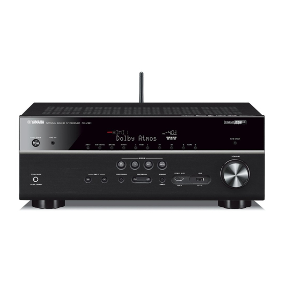
FRONT PANELS
RX-V681 Front Panel Overview
Illustrates the front panel layout and controls for the RX-V681 model.
REAR PANELS
RX-V681 Rear Panel Configurations
Illustrates rear panel connections for various RX-V681 models.
RX-A760 Rear Panel Configurations
Illustrates rear panel connections for various RX-A760 models.
REMOTE CONTROL PANEL
RAV537 Remote Control Layout
Details the buttons and functions of the RAV537 remote control.
SPECIFICATIONS
Audio Section Specifications
Details electrical and performance specifications for the audio components.
Video Section Specifications
Details electrical and performance specifications for the video components.
INTERNAL VIEW
RX-V681 Internal Component Layout
Illustrates the top and front views of the RX-V681 internal component placement.
SERVICE PRECAUTIONS
Safety Measures During Servicing
Highlights high voltage warnings and capacitor discharge procedures.
DISASSEMBLY PROCEDURES
RX-V681 Disassembly Steps
Procedures for removing the top cover and front panel unit.
RX-A760 Disassembly Steps
Procedures for removing the top cover and front panel unit for RX-A760.
UPDATING FIRMWARE
Firmware Update Procedures
Details on updating firmware via Internet or USB, including required tools.
Troubleshooting Firmware Update Errors
Lists common error messages and their meanings during firmware updates.
SELF-DIAGNOSTIC FUNCTION
Audio System Self-Diagnostics
Checks audio signal routes via DSP and PURE DIRECT modes.
Video System Self-Diagnostics
Checks analog and digital video signal routes, including HDMI.
Communication System Self-Diagnostics
Verifies communication and bus line connections on DIGITAL P.C.B.
System and Version System Diagnostics
Displays model, destination, firmware, and checksum versions.
POWER AMPLIFIER ADJUSTMENT
Voltage Adjustment Procedure
Details voltage confirmation and adjustment across specific terminals.
IC DATA
IC90: TMPM462F15FG Microprocessor
Provides pin connection diagram and details for the main microprocessor.
BLOCK DIAGRAMS
AUDIO Section Block Diagram
Illustrates the signal flow for audio processing and output.
DIGITAL P.C.B. Section Block Diagram
Shows the digital signal processing and connectivity on the digital PCB.
VIDEO Section Block Diagram
Illustrates the signal path for video processing and output.
Power Supply Section Block Diagram
Shows the power distribution and regulation circuits.
WIRING DIAGRAM
Overall Assembly Wiring
Illustrates how internal cables are routed and connected.
PRINTED CIRCUIT BOARDS
DIGITAL PCB Layouts
Shows component placement on DIGITAL (1) and DIGITAL (2) PCBs.
OPERATION PCB Layouts
Shows component placement on OPERATION PCBs.
MAIN PCB Layouts
Shows component placement on MAIN PCBs.
PIN CONNECTION DIAGRAMS
IC Pinout Diagrams
Provides pin configurations for various integrated circuits.
SCHEMATIC DIAGRAMS
DIGITAL Section Schematics
Detailed circuit diagrams for digital signal processing.
VIDEO Section Schematics
Detailed circuit diagrams for video signal paths.
AUDIO Section Schematics
Detailed circuit diagrams for audio signal paths.
Power Supply Section Schematics
Detailed circuit diagrams for the power supply unit.
REPLACEMENT PARTS LIST
Electrical Component Parts
Lists electrical components with part numbers, descriptions, and markets.
OVERALL ASSEMBLY
RX-V681 Overall Assembly Diagram
Exploded view showing the physical arrangement of major components.
RX-A760 Overall Assembly Diagram
Exploded view showing the physical arrangement of major components.
REMOTE CONTROL
RAV537 Remote Control Layout
Details the buttons and functions of the RAV537 remote control.
Remote Control Key Code Mapping
Maps remote control buttons to their corresponding ID codes.
FIRMWARE UPDATING PROCEDURE
Firmware Update Through the Internet
Steps to update firmware using an internet connection.
Firmware Update by USB
Steps to update firmware using a USB thumb drive.
Troubleshooting
Firmware Update Error Messages
Identifies and explains error messages during firmware updates.
Firmware Update Not Starting
Provides recovery methods for issues preventing firmware update.
Need help?
Do you have a question about the RX-A760 and is the answer not in the manual?
Questions and answers