
Related Manuals for Speck Fader 1


Summarization of Contents
Chapter 1 Introduction
General Description
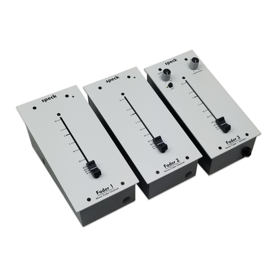
Explains the One Fader series, its models, and analog signal path features.
Standard Accessories
Lists items included with the One Fader units, like power modules and manuals.
Chapter 2 Installation
General
Provides basic installation guidance for the One Fader and power module.
Unpacking & Inspection
Details how to check the unit for damage upon arrival.
Cleaning
Instructions for safely cleaning the device surfaces without causing damage.
Mechanical Installation
Guidance on desktop placement for optimal viewing and access.
Power Module Installation
How to connect the external 16 VAC power module to the unit.
Power Module Mounting location
Recommends placement for the power module away from electronics.
Physical Placement of Adjacent Equipment
Advice on avoiding EMI/RFI interference from other gear.
Chapter 3 Fader 1 Operation
Overview
Introduces the Fader 1 and its controls and connectors.
Hooking up the Fader 1
Recommendations for using high-quality audio cables for optimal performance.
Signal Flow Diagram for the Fader 1
Visual representation of the audio path and signal flow within the unit.
Fader 1 Top Panel
Describes the controls and indicators on the front of the Fader 1 unit.
Fader 1 Rear Panel
Details the connectors and ports located on the back of the Fader 1.
Gain Select
Explains the jumper settings for adjusting input gain levels on the Fader 1.
Specifications
Lists technical details, including impedance, levels, frequency response, and dimensions.
Chapter 4 Fader 2 Operation
Overview
Introduces the Fader 2 stereo unit and its operational aspects.
Hooking up the Fader 2
Guidance on selecting appropriate audio cables for the stereo fader.
Signal Flow Diagram for the Fader 2
Illustrates the stereo signal path and component connections.
Fader 2 Top Panel
Describes the controls and indicators on the front of the Fader 2 unit.
Fader 2 Rear Panel
Details the connectors and ports located on the back of the Fader 2 unit.
Gain Select
Explains the jumper settings for adjusting input gain levels on the Fader 2.
Specifications
Lists technical details for the Fader 2, including audio performance and dimensions.
Chapter 5 Fader 3 Operation
Overview
Introduces the Fader 3 stereo unit with monitor capabilities.
Hooking up the Fader 3
Recommendations for connecting the Fader 3 using quality audio cables.
Signal Flow Diagram For Fader 3
Visualizes the stereo signal path, monitor, and headphone routing.
Fader 3 Top Panel
Describes the controls on the front of the Fader 3, including fader, monitor, and headphone.
Fader 3 Rear Panel
Details the connectors and ports on the back of the Fader 3 unit.
Gain Select
Explains the jumper settings for adjusting input gain levels on the Fader 3.
Specifications
Lists technical details for the Fader 3, including audio performance and dimensions.
Need help?
Do you have a question about the Fader 1 and is the answer not in the manual?
Questions and answers