
Related Manuals for Speck One Fader Series


Summary of Contents for Speck One Fader Series
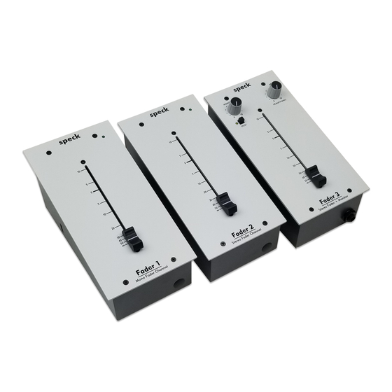
- Page 1 One Fader Series Reference Manual for Models: Fader 1 Operation section starts on page 7 Fader 2 Operation section starts on page 13 Fader 3 Operation section starts on page 19 speck electronics...
- Page 3 Warranty Speck Electronics products are warranted to the original owner to be free of defects in material or workmanship. This warranty does not apply to any product subject to accident, misuse, neglect, or failure to comply with normal maintenance procedures, or if the serial number has been defaced, altered, or removed;...
-
Page 4: Table Of Contents
Contents Chapter 1 Introduction General Description ............Standard Accessories ............Chapter 2 Installation General ................Unpacking and Inspection ..........Cleaning ................Mechanical Installation ............Power Module Installation ..........Power Module Mounting Location ........Physical Placement of Adjacent Equipment ...... Chapter 3 Fader 1 Operation Overview ................ -
Page 5: Chapter 1 Introduction
If you are unfamiliar with audio equipment or audio signal flow, it is recommended that you read this manual. If you have any questions regarding this or any Speck product, do not hesitate to contact Speck Electronics. Speck Electronics 341 E. -
Page 6: Standard Accessories
Chapter 1 Introduction Section The One Fader Series is available in three models: Fader 1 - Mono Fader (See page 7 for the operation section) Add the Fader 1 (Mono Fader) to your 500 module channel strip, to your hybrid recording signal path, or for "Riding the Fader"... -
Page 7: General
If the product is to be shipped to Speck Electronics for service or repair, contact Speck Electronics for a Return Merchandise Authorization (RMA). Include the model number and serial number of the product. -
Page 8: Power Module Installation
AC receptacle. The PS4-F power module has an internal “one shot” thermal fuse. Fuse replacement is not possible with this module. If it has been determined that the power module has failed, contact Speck Electronics for a factory replacement at +760-723-4281. -
Page 9: Power Module Mounting Location
Chapter 2 Installation Section Power Module Mounting location One of the primary reasons that the PS4-F power module is external is to insure that it maintains a safe distance from the active electronics of the One Fader. It is recommended that the power module be located at a reasonable distance from the One Fader and audio cables. - Page 10 Chapter 2 Installation Section ~ This page left intentionally blank ~...
-
Page 11: Overview
Chapter 3 Fader 1 Operation Section Operation - Fader 1 Overview In this section we will give you basic information on the operation of the Fader 1 (F.1.) and adequately describe its controls and connectors. The information in this section of the manual is intended to help with the technical process when using your F.1. - Page 12 Chapter 3 Fader 1 Operation Section Signal Flow Diagram for the Fader 1 Use the channel signal flow diagram shown below as a reference when reading the descriptions of the controls and connectors [1] through [6] in this chapter. MONO FADER BALANCED BALANCED...
- Page 13 Chapter 3 Fader 1 Operation Section Fader 1 Top Panel 1. Mono Fader This mono 100mm slide fader adjusts the level of the F.1. channel and has a range of ∞dB to 10dB. The operation of the slide fader adjusts the level to the XLR line output.
- Page 14 Chapter 3 Fader 1 Operation Section Fader 1 Rear Panel 16VAC 16 VAC PIN 1 PIN 2 16 VAC PIN 3 PIN 4 Power Inlet Pins 3. Power Inlet The cable from the PS4-F power module connects to this 4 pin square connector. This connector and its respective plug are keyed so they will only fit in one direction.
-
Page 15: Gain Select
Chapter 3 Fader 1 Operation Section 6. Gain Select The Fader 1 has three gain settings available: 0dB, 6dB, and 10dB. The factory default setting is for 0dB of gain. The gain select jumper is located on the right side of the chassis as shown below. Fader Input to Fader Output Gain With a balanced +4dBu signal present at the XLR line input, the fader set to the “0”... -
Page 16: Specifications
Chapter 3 Fader 1 Operation Section Specifications Line input impedance 30K ohms Balanced Unbalanced 15K ohms Maximum input level +28dBu Output Impedance 60 ohms +28dBu (Balanced) Maximum output level (2k load) +22dBu (Unbalanced) Frequency Response (10 dB gain) 1Hz-94kHz (+0/-.5dB) THD+n +4dBu at line input, fader set to “10”... -
Page 17: Overview
Chapter 4 Fader 2 Operation Section Operation - Fader 2 Overview In this section we will give you basic information on the operation of the Fader 2 (F.2.) and adequately describe its controls and connectors. The information in this section of the manual is intended to help with the technical process when using your F.2. - Page 18 Chapter 4 Fader 2 Operation Section Signal Flow Diagram for the Fader 2 Use the channel signal flow diagram shown below as a reference when reading the descriptions of the controls and connectors [1] through [6] in this chapter. STEREO FADER BALANCED BALANCED...
- Page 19 Chapter 4 Fader 2 Operation Section Fader 2 Top Panel 1. Stereo Fader This stereo 100mm slide fader adjusts the level of the left and right channels and has a range of ∞dB to 10dB. The operation of the slide fader simultaneously adjusts the level to the left and right XLR line outputs.
- Page 20 Chapter 4 Fader 2 Operation Section Fader 2 Rear Panel 16VAC 16 VAC PIN 1 PIN 2 16 VAC PIN 3 PIN 4 Power Inlet Pins 3. Power Inlet The cable from the PS4-F power module connects to this 4 pin square connector. This connector and its respective plug are keyed so they will only fit in one direction.
-
Page 21: Gain Select
Chapter 4 Fader 2 Operation Section 6. Gain Select The Fader 2 has three gain settings available: 0dB, 6dB, and 10dB. The factory default setting is for 0dB of gain. The gain select jumpers for the left and right channels are located on the respective left and right sides of the chassis as shown below. -
Page 22: Specifications
Chapter 4 Fader 2 Operation Section Specifications Line input impedance 30K ohms Balanced Unbalanced 15K ohms Maximum input level +28dBu Output Impedance 60 ohms +28dBu (Balanced) Maximum output level (2k load) +22dBu (Unbalanced) Frequency Response (10 dB gain) 1Hz-94kHz (+0/-.5dB) THD+n +4dBu at line input, fader set to “10”... -
Page 23: Overview
Chapter 5 Fader 3 Operation Section Operation - Fader 3 Overview In this section we will give you basic information on the operation of the Fader 3 (F.3.) and adequately describe its controls and connectors. The information in this section of the manual is intended to help with the technical process when using your F.3. -
Page 24: Signal Flow Diagram - Fader
Chapter 5 Fader 3 Operation Section Signal Flow Diagram For Fader 3 Use this channel signal flow diagram shown below as a reference when reading the descriptions of the controls and connectors [1] through [11] in this chapter. STEREO FADER BALANCED BALANCED INPUT-LEFT... - Page 25 Chapter 5 Fader 3 Operation Section Fader 3 Top Panel 1. Stereo Fader This stereo 100mm slide fader adjusts the level of the left and right channels and has a range of ∞dB to 10dB. The operation of the slide fader simultaneously adjusts the level to the left and right XLR line outputs.
- Page 26 Chapter 5 Fader 3 Operation Section Fader 3 Rear Panel 16VAC 16 VAC PIN 1 PIN 2 16 VAC PIN 3 PIN 4 Power Inlet Pins 7. Power Inlet The cable from the PS4-F power module connects to this 4-pin square connector. This connector and its respective plug are keyed so they will only fit in one direction.
-
Page 27: Gain Select
Chapter 5 Fader 3 Operation Section 11. Gain Select The Fader 3 has three gain settings available: 0dB, 6dB, and 10dB. The factory default setting is for 0dB of gain. The gain select jumpers for the left and right channels are located on the respective left and right sides of the chassis as shown below. - Page 28 Chapter 5 Fader 3 Operation Section Specifications Line input impedance 30K ohms Balanced Unbalanced 15K ohms Maximum input level +28dBu Output Impedance All Active-balanced outputs 60 ohms Headphone Impedance 75 ohms Maximum output level (2k load) +28dBu (Balanced) +22dBu (Unbalanced) Frequency Response (10 dB gain) Fader line input to fader line output 1Hz-94kHz (+0/-.5dB)
Need help?
Do you have a question about the One Fader Series and is the answer not in the manual?
Questions and answers