Advertisement
Quick Links
EC Declaration of Conformity
We;
Amplifier Research
160 School House Road
Souderton, Pa. 18964
declare that as of 1997, our product(s);
the Model 100A250 series amplifiers
to which this declaration relates is in compliance with the requirements of the EEC EMC Directive
(89/336/EEC) and Low Voltage Directive (73/23/EEC) in accordance with the relative standards listed
below:
EMC:
EN 50082-2 : 1995
Electromagnetic compatibility - Generic immunity standard
Part 2: Industrial environment
EN 55011 : 1991
Electromagnetic emissions requirements for Industrial, Scientific and Medical
(ISM) Equipment
Group 1, Class A
Safety:
IEC 1010-1 : 1990 + A1, A2
The CE marking is affixed on the device according to the EC Directives.
Donald R. Shepherd
President
Advertisement

Related Manuals for Amplifier Research 100A250A


Summary of Contents for Amplifier Research 100A250A
- Page 1 Souderton, Pa. 18964 declare that as of 1997, our product(s); the Model 100A250 series amplifiers to which this declaration relates is in compliance with the requirements of the EEC EMC Directive (89/336/EEC) and Low Voltage Directive (73/23/EEC) in accordance with the relative standards listed...
- Page 2 Model 100A250A Manual Text TABLE OF CONTENTS SECTION I: GENERAL INFORMATION General Description ..............1-1 Power Supplies .................1-1 Specifications................1-1 SECTION II: OPERATING INSTRUCTIONS General ................2-1 Amplifier Operation............2-2 2.2.1 Local Operation ................2-2 2.2.2 Remote Operation ..............2-2 SECTION III: THEORY OF OPERATION Introduction ................3-1 Driver Amplifier Section ............3-1 Final Amplifier Section...............3-1 Power Supply ................3-2...
- Page 3 Model 100A250A Manual Text SECTION V: REPLACEABLE PARTS ( CONTINUED Circuit Designators ....................5-1 Manufacturers’ Abbreviation Listing ...........5-2 Master List ................5-3 Schematics and Bills of Material (BOMs) ........5-3 A: S ....A-1 PPENDIX TANDARD BBREVIATIONS FOR ANUFACTURERS SECTION VI: RECOMMENDED SPARE PARTS Level of Maintenance ..............6-1 ARRANTIES IMITATION OF...
- Page 4 800 watts. A primary circuit breaker is provided. The output stage is protected by over current sensing and over temperature sensing circuits which shut down the power supplies under fault conditions. PECIFICATIONS Refer to the Amplifier Research Data Sheet on the next page for detailed specifications. REV -...
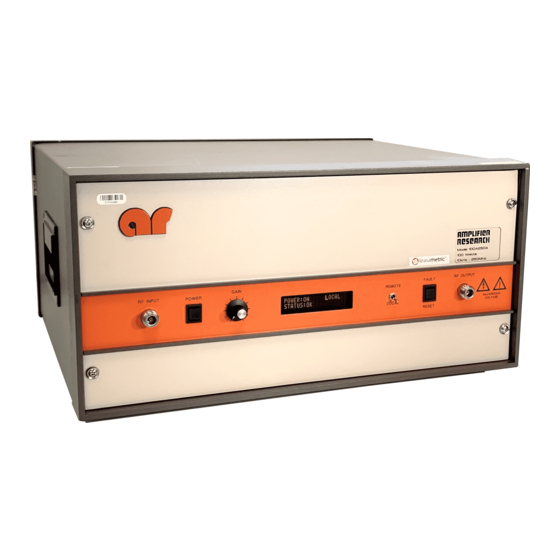
- Page 5 Model 100A250A Manual Text SECTION II OPERATING INSTRUCTIONS ENERAL Operation of the Model 100A250A broadband RF amplifier is simple. The input signal, whether swept or fixed in frequency, is fed into the jack marked “INPUT”, and the amplifier’s output signal is taken from the jack labeled “OUTPUT”.
- Page 6 Model 100A250A Manual Text AMPLIFIER OPERATION Figure 2.1 shows the Model 100A250A in pictorial form. FIGURE 2.1 AMPLIFIER OPERATION 2.2.1 Local Operation Power-up Sequence: 1. Connect the input signal to the unit’s RF INPUT connector. The input signal level should be 0dBm maximum.
- Page 7 Model 100A250A Manual Text 2.2.2.2 Selecting Remote Operation The Model 100A250A can be placed in the remote operation mode at any time by switching the FUNCTION switch on the front panel to the REMOTE position. In this mode, control is transferred to the selected remote interface and all front panel controls are inoperative with the exception of the FUNCTION switch.
- Page 8 Model 100A250A Manual Text 2.2.2 Remote Operation (continued) 2.2.2.4.2 IEEE-488 device address selection (continued) Table 2-1 IEEE-488 Device Address Selection Device Address Switch 5 Switch 4 Switch 3 Switch 2 Switch 1 off (0) off (0) off (0) off (0) on (1) off (0) off (0)
- Page 9 Model 100A250A Manual Text 2.2.2 Remote Operation (continued) 2.2.2.6 IEEE-488 Communications (continued) Table 2-2 Remote Error Codes/Messages IEEE-488 Serial Poll Model 100A250A FAULT RS-232 Response (STB) Error (binary/decimal) Message (01000001) 65 BPM FAULT (01000010) 66 THERMAL FAULT (01000100) 68 INTERLOCK FAULT (01001000) 72 PS1 FAULT (01010000) 80...
- Page 10 Model 100A250A Manual Text 2.2.2 Remote Operation (continued) 2.2.2.7 RS-232 Communications (continued) Table 2-3 RS-232 Connector Pin-Outs Pin No. Signal Data Direction* Description < Device Carrier Detect < Receive Data > Transmit Data > Data Terminal Ready Ground No Connection >...
- Page 11 Model 100A250A Manual Text 2.2.2 Remote Operation (continued) 2.2.2.8 Remote Commands (continued) 2.2.2.8.1 Power On/Off Controls the power on/off state of the Model 100A250A. Syntax: Px Parameters: 0 = power off 1 = power on Example: To turn the power on, send the following command: P1<LF>...
- Page 12 Model 100A250A Manual Text SECTION III THEORY OF OPERATION INTRODUCTION The Model 100A250A amplifier consists essentially of a push-pull output stage of broadband MOSFET transistors driven by a 10 watt driver amplifier. Overall power gain of the amplifier is a minimum of +50dB for 1 milliwatt input.
- Page 13 Model 100A250A Manual Text POWER SUPPLY Refer to "Schematic Diagram Number 1010659, Power Supply". Input AC power is fed through RFI Filter FL1 before being switched by the circuit breaker CB1. The AC input power is fed from CB1 to the three switching power supplies, PS1, PS2, PS3. The three switching supplies work on line voltages of 90 to 132 VAC and 180 to 264 VAC 50/60 Hz.
- Page 14 Small bias changes may ruin the amplifier due to excessive dissipation or transients. Components within Amplifier Research instruments are conservatively operated to provide maximum instrument reliability. In spite of this, parts within an instrument may fail. Usually, the instrument must be immediately repaired with a minimum of "down time".
- Page 15 Model 100A250A Manual Text TROUBLESHOOTING The techniques used in troubleshooting solid state instruments are similar to those used in vacuum tube instruments. For instance, a good way to start troubleshooting is to check the supply voltage at the amplifier supply voltage terminal.
- Page 16 The amplifier should change state every time the POWER switch is depressed. 4.3.1.7 If all voltages are correct and the unit still does not operate, contact Amplifier Research to arrange for repair or replacement of the A4 Operate/Control Board. 4.3.2 The Unit Cannot be Operated Remotely 4.3.2.1...
- Page 17 If all of the above voltages are correct and the unit still will not reset, check for defective wiring and/or PWB connections, then try the RESET switch again. If the unit still will not reset, the A4 Operate/Control Board is defective. Contact Amplifier Research to arrange for repair or replacement of the A4 Operate/Control Board.
- Page 18 Model 100A250A Manual Text 4.3.5 Voltage/Amplifier Faults (Schematic Diagram Nos. 1010659) The model 100A250A fault circuits sense voltage faults from PS1 (+15V) and PS2 (+15V). They also sense an over current fault in the final amplifier stage. 4.3.5.1 Power Supply Faults (Schematic Diagram 1010659). PS1 and PS2 send BUSS OK signals to the operate/control board (A4).
- Page 19 Model 100A250A Manual Text REV -...
Need help?
Do you have a question about the 100A250A and is the answer not in the manual?
Questions and answers