Table of Contents
Advertisement
Quick Links
Advertisement
Table of Contents

Related Manuals for STS G2


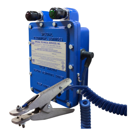
Summarization of Contents
Model Designation
Model Prefix
Prefix 'G' indicates the STS 300 Series Electronic Indicating Ground Assembly.
Voltage Code
Code specifies operating voltage, e.g., 2 for 120VAC, 4 for 240VAC.
Indicator Light Type
Designates indicator light type: L for LED, I for Incandescent.
Cable Type
Indicates cable configuration: C for Coil, S for Straight.
Cable Length
Specifies cable length in feet, e.g., 25.
Clamp Style
Denotes the type of clamp used, e.g., KA.
Additional Options
Placeholder '-XXX' for any extra options or accessories.
Installation and Mounting
General Installation
Installation by licensed, qualified person per applicable codes.
Cover Warning
Keep cover tightly closed when circuits are energized.
Enclosure Access
Always disconnect power and ventilate before opening enclosure.
Mounting Holes
Four 5/16"-18 holes for securing to Unistrut support.
Seal Fitting Requirement
Seal fitting required before conduit entry, filled with sealing compound.
Cover Bolt Torque
Cover bolts (5/16"-18) torque to 11 ft-lb (1.24 N/m).
Electrical Connections
Supply Voltage Connection
Connect supply voltage to terminals 1 & 2.
Auxiliary Contacts
Use NO/NC contacts for interlocks, not direct motor loads.
Optional Power Switch
An optional switch can disconnect power for extended bulb life.
Operation and Care
Grounding Clamp Attachment
Attach clamp to metal frame of vehicle, vessel, railcar, etc.
Indicator Light Status
Red light off, green light on for proper ground.
Auxiliary Contacts Operation
Auxiliary contacts change state, allowing equipment operation.
Indicator Light Logic
Red ON/Green OFF: No ground. Red OFF/Green ON: Grounded.
Maintenance Inspection
Inspect ground cables for damage and hardware for tightness.
Technical Specifications
Monitoring System
Details on power supply, rating, temperature, and enclosure.
Monitoring Circuit
Specifications for loop resistance and output relay contacts.
Integrity Lights
Indicator lights for status: Red (Non-permissive), Green (Permissive).
Integrity Ground Cable
Details on cable type, conductors, and length.
Operator Cable
Specifications for coil cable type, conductors, and length.
Grounding Clamp
Information on clamp contacts and body material.
Need help?
Do you have a question about the G2 and is the answer not in the manual?
Questions and answers