Table of Contents
Advertisement
Quick Links
Advertisement
Table of Contents

Subscribe to Our Youtube Channel
Related Manuals for STS 300 Series


Summary of Contents for STS 300 Series
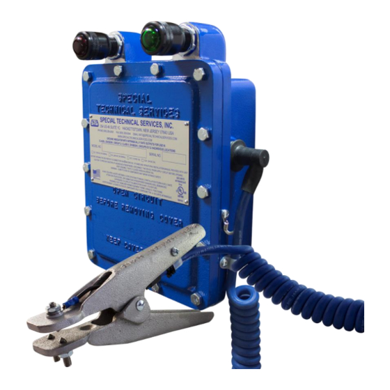
- Page 1 Read entire manual before installing STS 300 Series Electronic Indicating Ground Assembly Installation and Operating Instructions Special Technical Services Inc. 354 US Highway 46 Suite 1C Hackettstown, NJ 07840 USA T +1 609-259-2626 F +1 609-259-0044 Email info@specialtechnicalservices.com...
-
Page 2: Model Designation
Class I, Group D; Class II, Groups E, F, and G hazardous locations. The STS 300 will indicate a proper ground has been established on a vehicle or drum for the handling of hazardous materials such as flammable liquids like gasoline or products that generate dust. The ground clamp will also safely dissipate any unwanted static charge. -
Page 3: Electrical Connections
P a g e (4) 5/16"-18 Threaded Mounting 4.500in Holes [114.300mm] 1/2" Deep 3/4"-14 NPT Conduit Opening 11.125in [282.575mm] 4.375in [111.125mm] 5.000in [127mm] 3.738in [85.69mm] Electrical Connections The supply voltage should be in accordance with the rating specified on the nameplate on the front cover. Connect supply voltage to terminals 1 &... -
Page 4: Operation And Care
P a g e PERMISSIVE LOCKOUT GROUND (RED) (GREEN) INSTALL WITH CASE GROUND AND IG STUD WIRES RED AND GREEN MUST BE CONNECTED SEPARATELY LIGHTS ON TOP AT GROUND BUS GROUND ROD FOR REMOTE LOCATIONS CASE GROUND AND IG STUD WIRES WHITE WIRE MUST BE CONNECTED SEPARATELY 10-32 3/8"... -
Page 5: Replacement Parts List
Aluminum GAT C lamp with Isolated Points DMS-14 STS RD14 Deadman Switch,Standard G40-IP Bronze Ground C lamp with Isolated Points DMS-15 STS RD15 Deadman Switch,C ast Aluminum Clamp Replacement Parts Retractable Cable Reel Part Number Description Part Number Duty Description K7817512 K7817512 1/2"... -
Page 6: Maintenance Schedule
P a g e Maintenance Schedule TASKS TO BE PERFORMED Daily Weekly Monthly Annually External Assembly Check enclosure for damage Check enclosure cover bolts are free from excessive corrosion Verify breather is installed and undamaged Verify red lens cap is not cracked or damaged Verify green lens cap is not cracked or damaged Verify neoprene boots are installed properly on both sides of the enclosure Verify neoprene boots are not damaged or cracked on the enclosure... -
Page 7: Troubleshooting
P a g e Troubleshooting Condition Possible Cause • No power to control unit No lights ON • Blown bulb • Input fuse F2 blown • Fault or damage in controller wiring or PCB • Incorrect installation of lens caps (Red on the left, Green on the right) Green light ON when the •... -
Page 8: Technical Specifications
P a g e Technical Specifications Monitoring System Power Supply 120VAC Model: 102-130VAC, 50/60Hz (marked on nameplate) 240VAC Model: 204-240VAC, 50/60Hz 12VDC Model: 9-15VDC 24VDC Model: 18-30VDC Power Rating 5 Watts Temperature range -40°F to 130°F (-40°C to 55°C) Fused Protection 5 Amps Enclosure Type NEMA 7, 8, &...
Need help?
Do you have a question about the 300 Series and is the answer not in the manual?
Questions and answers