Table of Contents
Advertisement
Sheath Fault Locator
SERVICE CENTER, SALES AND TECHNICAL SUPPORT INFORMATION
Corporate Headquarters
3251 Olcott Street
Santa Clara, CA 95054
800-446-3392
408-734-1400 Direct
408-734-1415 Fax
www.metrotech.com
sales@metrotech.com
Warranty: One year. Specifications Subject to change without notice, ISO 9001:2000 Certified. Copyright 2008. All Rights Reserved.
9800XT™ SFL2
Metrotech Eastern U.S. Service Center
1824 Murfreesboro Road, Ste. 104
Nashville, TN 37217
800-624-6210
615-366-7323 Direct
615-360-9855 Fax
nashville@metrotech.com
OPERATIONS MANUAL
Metrotech European Service Center
Seba KMT
Dr. Herbert Iann St. 6
96148 Baunach, Germany
+49 9544 680
+49 9544 2273 Fax
service@sebakmt.com
Rev 12/01/07
Advertisement
Table of Contents

Related Manuals for Metrotech 9860XT FXT


Summary of Contents for Metrotech 9860XT FXT
- Page 1 9800XT™ SFL2 OPERATIONS MANUAL Sheath Fault Locator SERVICE CENTER, SALES AND TECHNICAL SUPPORT INFORMATION Corporate Headquarters Metrotech Eastern U.S. Service Center Metrotech European Service Center 3251 Olcott Street 1824 Murfreesboro Road, Ste. 104 Seba KMT Santa Clara, CA 95054 Nashville, TN 37217 Dr.
- Page 2 ISO 9001 CERTIFIED Metrotech has received ISO 9001 Quality Management System Certification. Metrotech adheres to the quality standard guidelines of ISO 9001 and ensures quality in its design/development, production, installation, and servicing disciplines. © Metrotech Corporation 2005-2008 Metrotech Corporation 3251 Olcott Street Santa Clara, CA 95054 Tel: 1.800.446.3392;...
-
Page 3: Table Of Contents
TABLE OF CONTENTS List of Illustrations ………………………………………………………. .1 Introduction …….……..………………………….…………………………. 2 Safety Precautions ………………………………………………………… ..3 3 9800XT SFL-2 Quick Start Guide for the Experienced User ………. .4 4 9800XT SFL-2 Equipment ………………………………………..….….. .10 4.1 Standard Equipment………………………………………..….….10 4.2 Optional Accessories……………………………………..…. . ….12 4.3 Technical Specifications…………………………………….. - Page 4 8 Advanced Techniques …...….………………………………….…...……..33 8.1 Faults Under Inaccessible Surfaces…..………………………...33 8.1.1 Perpendicular Method………………………………………..……..33 8.1.2 Triangulation Method………….. .………………………… ………34 Faults Under Pavement…..……………………………… ……..35 Long Distance Tracing……..………… .. …… ……………35 High and Low Impedance Faults…....……………..36 Multiple Faults…….
-
Page 5: List Of Illustrations
LIST OF ILLUSTRATIONS Figure 3-1: Fault Resistance Scale........4 Figure 3-2: Clamping Black Lead to Ground Rod…..…….. -
Page 6: Introduction
INTRODUCTION The Metrotech 9800SFL Sheath Fault Locator system is designed to detect and pinpoint sheath and other conductor faults that are in direct contact with the earth. The 9800SFL offers these unique features: ♦ Fault level measurement at the Transmitter ♦... -
Page 7: Safety Precautions
SAFETY PRECAUTIONS Metrotech Utility Line and Sheath Fault Locators are intended for use by utility and contractor professionals. Safety hazards for underground utility access areas include electrical shock, explosive gases, and toxic fumes as well as potential influence on communications and control systems such as traffic control and railroad crossings. -
Page 8: 9800Xt Sfl-2 Quick Start Guide For The Experienced User
9800XT SFL-2 SHEATH FAULT LOCATOR QUICK START FOR THE EXPERIENCED USER Check Batteries Prior to Departing for the Field Check the batteries in the Transmitter, Receiver, and A-Frame. Replace/recharge if necessary. Turn the instruments off. Ensure all conductors are de-energized Lift Grounds Lift Grounds (of all conductors in the circuit) at both ends of the faulted cable section. -
Page 9: Figure 3-2: Clamping Black Lead To Ground Rod
Figure 3-2: Clamping Black Lead to Ground Rod Figure 3-3: Clamping Red Lead to Conductor Use the 9800XT Line Locator Receiver to Trace the Cable Trace and mark the cable as you proceed towards the fault. Figure 3-4: Locating the Targeted Cable... -
Page 10: Figure 3-5: Positioning Of A-Frame Receiver For Synchronization
Synchronize the A-Frame Receiver and establish reference value of fault (A-Frame receiver has a one-color band above each spike (Black or White) 1 Hold the A-Frame Receiver so the spike with the black band is about 2 steps away from the ground rod and the spike with the white band is in-line with the targeted cable. -
Page 11: Figure 3-6: Locating The Cable Fault With A-Frame Receiver
Figure 3-6 : Locating the Cable Fault with A-Frame Receiver... - Page 12 The higher the active number the larger the fault. If you have difficulty with your Metrotech SFL-2 Sheath Fault Locator, check the manual for additional tips. For Assistance, call us at 1-800-446-3392.
- Page 13 NOTE: This equipment has been tested and found to comply within limits for a Class B digital device, pursuant to Part 15 of the FCC Rules. These limits are designed to provide reasonable protection against harmful interference in residential installations. This equipment generates, uses, and can radiate radio frequency energy.
-
Page 14: 9800Xt Sfl-2 Equipment
MODEL 9800XT SFL EQUIPMENT Standard Equipment The SFL transmitter is an option to the 9860XT and 9890XT Locator System and is designated by the ‘F’ in the Part Number. When the SFL option is selected, the standard equipment may include: Part Model # Description Remarks... -
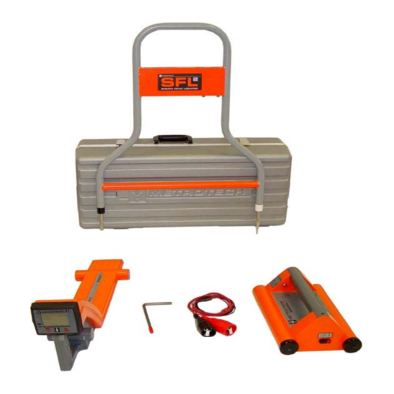
Page 15: Figure 4-1: Standard Equipment And Accessories
Figure 4-1: Standard Equipment and Accessories Standard: 1. 9800XT Receiver 2. 9800XT Transmitter 3. Conductive Attachments 4. Ground Rod 5. Carrying Case 6. SFL – 2 Receiver 7. Operation Manual Accessories: 8. MetroClamp 9. Flex-Sonde 10. High Power Sonde 11. Standard Power Sonde... -
Page 16: Optional Accessories
4.2 Optional Accessories Optional accessories available for the 9800XT Sheath Fault Locator are listed below: Part/Model # Description Remarks 4290 2” Metroclamp and For Inductive jumper cable Coupling or Cable ID 4490 4” Metroclamp and For Inductive jumper cable Coupling or Cable ID 4890 8”... -
Page 17: Technical Specifications
4.3 Technical Specifications TRANSMITTER Output Frequencies: Model Frequencies 9860XT* 4.8Hz, 9.82kHz, 82kHz 9890XT* 4.8Hz, 982Hz, 9.82kHz, 82kHz Audio Output: Pulsing tone to indicate Transmitter output is active. Line Tracing Ohmmeter: 0-2 kOhm Fault Metering: Continuous fault resistance monitoring 0 to 10M Ohm. Automatic ”Best”... - Page 18 Technical Specifications (4.3 cont’d) A-FRAME RECEIVER Frequency: 4.8 Hz Crystal Controlled Input Sensitivity: 5 MV Sensitivity Control: Automatic Dynamic Range: Bargraph 72 dB Output Indication: Bargraph LCD Flashing LCD arrows point to fault 12 segment LCD bar graph indicates signal level, each bar = 6dB. Battery: 9 V NEDA 1604 or equivalent.
- Page 19 Technical Specifications (4.3 cont’d) 9800XT Receiver Frequencies: Model Frequencies 9860XT Active - 9.82kHz, 82kHz Passive - 50/60Hz, 14-22kHz 9890XT Active - 982Hz, 9.82kHz, 82kHz Passive - 50/60Hz, 14-22kHz Depth Readout Accuracy: Passive-+(5% + 2”) under normal conditions Active- +(5% + 2”) under normal conditions Distance Sensitive Left/Right Guidance Real-Time Continuous Gain Adjustment and Manual Gain Control...
-
Page 20: Transmitter Controls And Indicators
Transmitter: Controls and Indicators WARNING When the Transmitter is set to “SFL”, the external OUTPUT JACKS produce high voltage. Do not touch these jacks, electrical shock will result! See Figure 4-2 for location of Transmitter controls and indicators described below: Figure 4-2: Transmitter Control Panel Output Clamp Jack Conductor Arrow... - Page 21 OUTPUT CLAMP JACK Insert the MetroClamp phone plug into this jack only. CONDUCTOR ARROW Align this arrow with your targeted conductor when you are locating in the Inductive mode. CHARGE JACK (Optional Feature) If you have purchased a 9800 XT with the Rechargeable NiCd Battery feature, your Transmitter will have a jack for connecting the Wall Mount Charger or the Vehicle Mount Charger.
-
Page 22: Transmitter Features
Transmitter: Features LCD BARGRAPH DISPLAY - The bar graph indicates four types of information: BATTERY STATUS - First 3 seconds the amount of Transmitter battery charge is indicated by the number of bars illuminated. CIRCUIT RESISTANCE - The blinking bar indicates, in ohms, the amount of signal resistance on your conductor and your faulted cable. - Page 23 POWER KNOB - The amount of transmitter signal output for each power setting changes according to which frequency you are using: Power Setting Frequency__________________ 982Hz 9.82kHz 82kHz L-Low 0.3 watts 0.3 watts 0.15 watts M-Medium 1 watt 1 watt 0.25 watts H-High 3 watts 3 watts...
-
Page 24: A-Frame Receiver Controls And Indicators
A-Frame Receiver Controls and Indicators See Figure 4-3 for location of Receiver controls described below: Bargraph On/Off Figure 4-3: A-Frame Controls and Indicators On/Off Button Push and release to turn “ON”. Push and release to turn “OFF”. LCD Bargraph Display: The bargraph indicates three types of Information: •... -
Page 25: Additional A-Frame Receiver Features
4.7 Additional A-Frame Receiver Features 4.7.1 Battery Access Plate Located on the underside of Receiver control panel. Remove the two thumbscrews to release the plate. See Figure 9-1 on page 37. 4.7.2 Conductive Pads The A-Frame Receiver is shipped with two protective foam pads with large washers attached to the Receiver probes. -
Page 26: Principles Of Operation
PRINCIPLES OF OPERATION 5.1 Functional Theory Even an experienced user needs to review the basics of sheath fault locating before proceeding. This will improve the changes of finding the fault and save valuable time. Comparing electrical current to water flowing through a pipe applies extremely well to fault locating. -
Page 27: Figure 5-1: Typical Sfl-2 Transmitter Connection
Figure 5-1: Typical SFL-2 Transmitter Connection Black Lead Red Lead Ground Rod Fault Faulty conductor open on both ends... -
Page 28: Earth Voltage Gradient
As current flows from the Transmitter and through the fault, an earth voltage gradient field is created. It is center is at the fault. This gradient field has a pattern such as that depicted in Figure 5-2. (Looks like the ripples in a pond when you throw a rock in, or the rings of the stump of a tree.) Figure 5-2: Signal Pattern Around Fault and Ground Point. - Page 29 This result can also occur midway between the ground spike and a fault and when the A- frame is exactly perpendicular to the fault. There is a return field around the Transmitter ground spike. As you move toward the fault, the bars and the active numerical number will decrease until you reach the midpoint between the fault and ground spikes.
-
Page 30: Multiple Fault Patterns
5.1.3 Multiple Fault Patterns The signal pattern created by two faults in a line is depicted in Figure 5-3. The two faults are shown without the ground point. Notice that from a distance the two faults will have the appearance of a single fault due to the equipotential circle around them both. As you get closer, the individual faults become apparent. -
Page 31: Checkout Procedure
Check Out Procedure Perform this instrument checkout procedure on a lawn prior to field site use. If grass or dirt is not available, indoor carpeting may be used. Check the Batteries. Turn the Transmitter “ON”. The transmitter LCD will display the battery charge status. - Page 32 Spread the Test Cables as Far Apart as Possible. Insert the ground spike and attach the black cable. Insert a screwdriver into the ground and connect the red cable to it. This will create a simulated fault. This test can also be done by pushing the metal end of the clamps directly into the ground so that they make electrical contact.
-
Page 33: Operation
7 OPERATION Check the batteries prior to going into the field. Follow the Transmitter battery check procedures as given on page 4. Turn the A-Frame Receiver “ON”. The solid bars indicate the battery level. If only one bar appears, replace the battery (1 each, 9 volt). The battery status is “ON” for 3 seconds at turn on. -
Page 34: Synchronize The A-Frame Receiver
Synchronize the A-Frame Receiver By synchronizing, the A-Frame memorizes the phase of the Transmitter signal. This allows it to recognize the reverse phase signal coming from the fault and direct you to it. Note: Resynchronize the Receiver every 45 minutes to maintain calibration. You may do this near the ground rod or near a fault. -
Page 35: Figure 7-2: Fault Confirmation
Figure 7-2: Fault Confirmation... -
Page 36: Confirm That A Fault Exists
7.5 Confirm that a fault exists. Remove the A-Frame from the ground. Rotate it 180 degrees and re-insert it into the ground. The arrows should reverse directions and point away from the ground spike. 7.6 Trace the cable with the 9800 Receiver. The 9800 Line Locators allows you to trace the line and search for the fault at the same time. -
Page 37: Advanced Techniques
8 Advanced Techniques 8.1 Faults Under Inaccessible Surfaces. When the faults exist beneath a paved or other inaccessible area, the fault may be located using one of the following methods. 8.1.1. Perpendicular Method. Carefully trace the location of the faulty conductor. Hold the A-Frame parallel to the cable path. -
Page 38: Triangulation Method
Triangulation Method. As shown in Figure 8-2, (the point where the signal strength is a minimum) if the A- Frame is positioned exactly on an equipotential circle, a perpendicular line from the center of the A-Frame will pass through the fault. The intersection of any two such perpendicular lines defines the fault location. -
Page 39: Faults Under Pavement
8.2 Faults Under Pavement Faults under pavement or other slightly conductive surfaces can be found using the foam pads supplied with the unit. Saturate the pads with water and insert the A-Frame spikes into the pads. Locate the fault as you normally would. Be sure to keep the pads as moist as possible, but do not let the water form a continuous puddle between the pads as this will short out the signal. -
Page 40: High And Low Impedance Faults
8.4 High and Low Impedance Faults. Before beginning a fault search it is a good idea to know the severity of the fault. This is measured in terms of it is resistance or impedance to ground. Faults where the ground is wet and/or a very large piece of the insulation is missing are found at the low end of the range (<500 ohms). -
Page 41: Maintenance
9 MAINTENANCE 9.1 Receiver Battery Replacement. Loosen the two thumbscrews located on the underside of the Receiver housing. Gently pull out battery door. Be careful not to pull on the battery wires. Remove battery from battery holder and disconnect battery. Reverse procedure for installing new battery. Connector Figure 9-1: Receiver Battery Replacement... -
Page 42: Service Center
Service Centers If the instrument does not function properly, replace the battery as described above. If the equipment still malfunctions, contact one of our Metrotech Customer Service departments for assistance: Metrotech West Coast Service Center 3251 Olcott Street Santa Clara, CA 95054... -
Page 43: Appendix
APPENDIX A1 APWA Marking Colors - The following color markings have been established by the American Public Works Association (APWA): Conductor Color Electric power lines, cables, or conduits _______________________________________________ Communication lines, cables, conduits, CATV Orange _______________________________________________ Gas, oil, petroleum, or other gaseous materials Yellow _______________________________________________... -
Page 44: Copyright
The information contained in this document is for informational purposes only and is subject to change without notice. Metrotech Corporation makes no warranty of any kind with regard to the information contained in this manual, including but not limited to the implied warranties of merchantability and fitness for a particular purpose. -
Page 45: Warranty
THERE ARE NO WARRANTIES, EXPRESSED OR IMPLIED, INCLUDING ANY WARRANTY OF MERCHANTABILITY, BEYOND THOSE STATED HEREIN. Metrotech warrants it is equipment to be free from defects in workmanship and material under normal and proper use and service for one year from date of purchase by original user.
Need help?
Do you have a question about the 9860XT FXT and is the answer not in the manual?
Questions and answers