Advertisement
Eng
Guía de instalación
E
Guide d'installation
F
Mechanical Installation
Eng
CU42E0
CU4200
TAMPER
CU42E0T - CU42E0G - CU4200T - CU4200G
CU42E0T00 - CU42E0G00 - CU4200T00 - CU4200G00
1
All contents current at time of publication.
SALTO Systems S.L. reserves the right to change availability of any
item in this catalog, its design, construction, and/or materials.
Installation guide
XS4 Controller
104
(4-1/8")
44
(1-3/4")
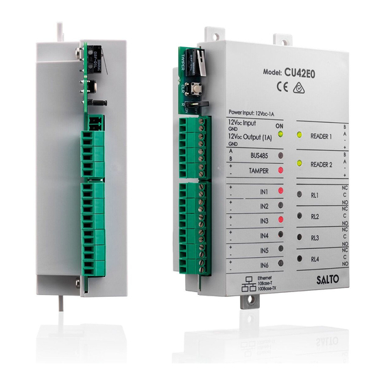
CU42E0
Model:
Power Input: 12V
-1A
DC
12V
Input
ON
DC
GND
READER 1
12V
Output (1A)
DC
GND
A
BUS485
B
READER 2
+
TAMPER
-
+
IN1
-
RL1
+
IN2
-
+
RL2
IN3
-
+
IN4
-
RL3
+
IN5
-
+
RL4
IN6
-
Ethernet
10Base-T
100Base-TX
Instalación mecánica
E
2
XS4 Controller
©
2017 SALTO Systems S.L.
43
(1-11/16")
B
A
B
A
NC
C
NO
NC
C
NO
NC
C
NO
NC
C
NO
10
(3/8")
F
Electric box with tamper switch.
Eng
Caja eléctrica con detector de intrusión o tamper.
E
Coffret électrique avec interrupteur anti sabotage.
F
3
CU42xx.. series
Installation mécanique
This installation type is not UL evaluated.
224901-ED2.- 07/07/2017
1/20
Advertisement
Table of Contents

Related Manuals for Salto XS4 CU42E0


Summarization of Contents
Factory Configuration
Input/Output Configuration Mapping
Details of factory default input and output configurations for various functions.
Electrical Characteristics
Operating Conditions and Power Specifications
Environmental conditions and power specifications including voltage and current.
Cable Recommendations
Recommended cable types for connecting various components like Ethernet and readers.
Installation Examples
Wiring Connection Examples
Diagrams illustrating general wiring connections and cable color codes.
RJ45 Reader Connection Example
Example of installing the CU4200 with RJ45 connectors for readers.
Device Configuration
Addressing the CU42E0
Steps to assign an IP address to the CU42E0, including DHCP and static options.
Dipswitch Settings
Offline Mode Setup
How to configure dipswitches for offline operation of CU4200.
Online Mode Addressing via BUS485
Using dipswitches for unique address assignment on BUS485.
Signaling and Status LEDs
Power and Communication Status LEDs
LED indicators for power, BUS485 communication, and tamper status.
Input/Output and Reader Status LEDs
LED indicators for input activation, reader communication, and relay status.
Need help?
Do you have a question about the XS4 CU42E0 and is the answer not in the manual?
Questions and answers