Advertisement
Quick Links
RUGBY MANUFACTURING CO.
INDUSTRIAL PARK
515 1st St. NE.
RUGBY, NORTH DAKOTA 58368
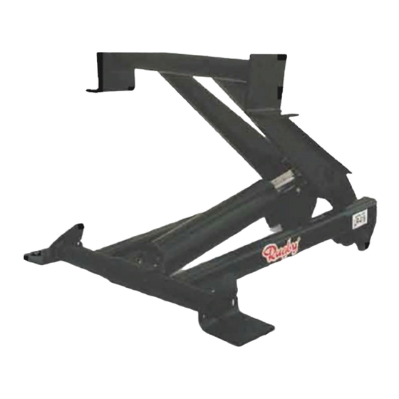
LR-416, LR-165, LR-25
INSTALLATION AND
OPERATION MANUAL
Hoist Installed: _____________________________
Hoist Serial #: ______________________________
Pump Installation and Operation Manual #: ______________
In Service Date: _____________________________
Dealer: ____________________________________
Address: ___________________________________
Dealer Phone Number: _______________________
Use this manual ONLY if installing or operating an LR-416, LR-165, or LR-25 hoist. This manual
should be kept in truck glove compartment for reference when needed.
Features LR-416 P/N 03 3021, LR-165 P/N 03 3018, LR-25 P/N 03 3019
FIRST EDITION: July 1, 1997
LATEST EDITION: N (July 28, 2020)
To Be Filled In By Installer
1656299
Advertisement

Related Manuals for Rugby LR-165


Summary of Contents for Rugby LR-165
- Page 1 Address: ___________________________________ Dealer Phone Number: _______________________ Use this manual ONLY if installing or operating an LR-416, LR-165, or LR-25 hoist. This manual should be kept in truck glove compartment for reference when needed. Features LR-416 P/N 03 3021, LR-165 P/N 03 3018, LR-25 P/N 03 3019...
- Page 2 Depending on the type of hydraulic system purchased, one of the above manuals will be included in every LR-416, LR-165,or LR-25 sold by Rugby Manufacturing Co. Before installing the hoist, be sure you have the proper manuals to do the job. If you do not have the correct manuals, contact Rugby Manufacturing Co.
- Page 3 "CAUTION" The hydraulic system supplied with a given hoist manufactured by Rugby Manufacturing Co. is made up of components (pump, valves, reservoir, hoses, cylinder, etc.) that are designed to be compatible with each other. If you substitute hydraulic components, it is your responsibility to BE SURE they are compatible with the other components supplied by Rugby Manufacturing Co.
- Page 4 WARNINGS: Warning: Not installing or operating equipment correctly can cause component damage or an accident which may cause injury or death. "Always" install and operate equipment in accordance with manufacturer's instructions. Read and understand this manual fully before proceeding. Warning: Welding, oxy-fuel cutting, or grinding sparks can cause fuel to ignite which in turn can lead to injury or death.
- Page 5 Capacities are based on water level, non-diminishing loads. Because of variations in truck equipment and cab axles (CA), the data contained in this sheet is provided only as a general guide.
- Page 6 Capacities are based on water level, non-diminishing loads. Because of variations in truck equipment and cab axles (CA), the data contained in this sheet is provided only as a general guide.
- Page 7 Capacities are based on water level, non-diminishing loads. Because of variations in truck equipment and cab axles (CA), the data contained in this sheet is provided only as a general guide.
- Page 8 Locate the hoist on the truck frame making sure to center the hoist right and left and to square the hoist with the truck frame. The LR-416, LR-165, and LR-25 are designed to rest on the truck frame as shown in their respective Figure 1. A portion of the hoist extends below the truck frame level;...
- Page 9 A listing of the Pump Installation & Operation Manuals is given on page #1 of this manual. Position and secure the liner (sleeper) to the truck frame. The LR-416 or LR-165 hoist requires at least 5 3/4" of clearance above the truck frame. As an example, if 4" long beams are on the truck body, a liner of at least 1 3/4"...
- Page 10 Position the rear hinge brackets against the long beams. Once in position, weld the rear hinge brackets to the body long beams as shown in Figure 6. Slide each of the lifting shafts against the inside of the channel long beam. Weld the lifting shaft to secure the shaft to the long beam as shown in Figure 7.
-
Page 12: Decal Location
DECAL LOCATION: Two 03 6039 "Danger" decals, as shown on this page, are supplied with each LR-416, LR-165, and LR-25. These decals must be positioned as shown in Figure 11. LOCATE 1 CAUTION DECAL (1656318) ON THE TRUCKS LEFT FRAME RAIL, AND LOCATE 1 CAUTION DECAL (1656318) ON THE TRUCKS RIGHT FRAME RAIL. - Page 13 LR-416 PARTS LIST ITEM PART # DESCRIPTION 1653827 SCREW, ½-13 X 1-1/2 HHC GR5 PLT 1620051 SCREW, ½-13 X 2-1/2 HHC GR8 PLT 1653838 SCREW, 5/8-11 X 4 HHC GR8 PLT 1653845 SET SCREW, 3/8-16 X 5/8 SQR HD BLK 1653860 NUT, ½-13 HEX GR5 STL PLT...
- Page 14 BRACKET, MOUNTING ANGLE 1653845 SET SCREW, 3/8-16 X 5/8 SQR HD BLK 1655676 SADDLE BRKT ASSY, SET, 416/165/25 1654905 COLLAR, 2.00 LOCK 1520370 FITTING, ¼-28” THREAD FORMING GREASE 1655695 BRACKET, LR-416/165/25 LIFT 1655044 CYLINDER PIN SHAFT, LR-165/25 1654927 HOIST FRAME, LR-165...
- Page 15 SADDLE BRKT ASSY, SET, 416/165/25 1654905 COLLAR, 2.00 LOCK 1520370 FITTING, ¼-28” THREAD FORMING GREASE 1655695 BRACKET, LR-416/165/25 LIFT 1655044 CYLINDER PIN SHAFT, LR-165/25 1655034 HOIST FRAME, LR-25 © 1997,1998, 2000, 2001, 2002, 2003, 2005, 2020 Rugby Manufacturing Co. s:\acaddwg\manuals\035753-M.p65...
Need help?
Do you have a question about the LR-165 and is the answer not in the manual?
Questions and answers