
Related Manuals for Konecranes SMV 25-1200B


Summary of Contents for Konecranes SMV 25-1200B
- Page 1 Instruction manual SMV 10 600B – 60 1500B Publ. no. 6196.082 1117, Version 02 Model range SMV 10-600B – SMV 60-1500B Instruction manual SMV 10 600B – 60 1500B Publ. no. 6196.082 1117, Version 02...
-
Page 2: Your Machine From Konecranes
The warranty/delivery report must be filled in and returned the manufacturer. to Konecranes Lifttrucks within a week after the first time of use in order for the warranty to be valid from the first time of For any optional equipment, please refer to the the user use. -
Page 3: Table Of Contents
TABLE OF CONTENTS Driving shaft, inspection and replacement of oil .... 78 Hydraulic system ............80 Lubrication ..............82 YOUR MACHINE FROM KONECRANES Inspection of the cooling system ........85 LIFTTRUCKS ..............2 Drive belt ............... 86 Technical remark .............. 2 Engine ................ -
Page 4: Safety Regulations
Safety regulations Instruction manual SMV 10 600B – 60 1500B Publ. no. 6196.082 1117, Version 02 SAFETY REGULATIONS SAFETY RULES • Lifting persons with the machine is prohibited. • Never exceed the lifting capacity of the machine – see the •... -
Page 5: Warning Texts And Important Information
Safety regulations WARNING TEXTS AND IMPORTANT INFORMATION Always read the instructions that follow the warning symbol or informative text. There are three different types of warning texts in the Important information is indicated by the abbreviation instruction manual. They are divided into different levels of NOTE. -
Page 6: Before Driving
Adhere to the guidelines and safety rules that are available for: Authorised dealers of Konecranes Lifttrucks may provide • using industrial machines, further information on this. • roads and work places, NORMS •... -
Page 7: Presentation Of The Machine
Presentation of the machine Instruction manual SMV 10 600B – 60 1500B Publ. no. 6196.082 1117, Version 02 PRESENTATION OF THE MACHINE The axial piston pumps together with a gear pump are fitted directly on the transmission. The gear pump builds up the accumulator pressure for the foot and parking brakes. -
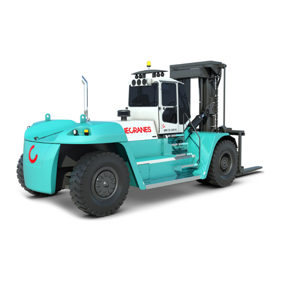
Page 8: Overview Of The Machine
Presentation of the machine OVERVIEW OF THE MACHINE 1. Mast 2. Fork carriage 3. Forks 4. Tilt cylinder 5. Lift cylinder 6. Drive axle 7. Engine hood 8. Steering axle 9. Counter weight 10. Driver's cabin Instruction manual SMV 10 600B – 60 1500B Publ. no. 6196.082 1117, Version 02... -
Page 9: Id-Plates And Serial Number
Presentation of the machine ID-PLATES AND SERIAL NUMBER 1. Mast number 2. Load capacity plate 3. Fork carriage number 4. Driving axle number 5. Chassis number 6. Transmission number 7. Engine number 8. Steering axle number Instruction manual SMV 10 600B – 60 1500B Publ. no. 6196.082 1117, Version 02... -
Page 10: Cabin Controls And Indicators
Presentation of the machine CABIN CONTROLS AND INDICATORS 1. Steering wheel 11. Declutch 2. Wiper windscreen 12. Cooling (AC) 3. Main beam/dipped beam 13. Recirculation 4. Horn 14. Heater controls 5. Driving direction indicator 15. Fan 6. Windscreen washer 16. Instrument panel and switches 7. -
Page 11: Warning Indicators And Gauges
Presentation of the machine WARNING INDICATORS AND GAUGES 1. Work light mast 11. Lever steering (optional) 2. Work light roof 12. Central lubrication (optional) 3. Work light extra 13. Central lubrication (optional) 4. Driving light 14. Activation diagnostics engine (optional) 5. -
Page 12: Description Of Drive Monitor Iqan Md3
Presentation of the machine DESCRIPTION OF DRIVE MONITOR IQAN MD3 The function of the trip computer is to, by using information from different sensors, analogue and digital signals, optimally control the hydraulic system and drive line. The driver has a total overview of the activities of the machine during operation. - Page 13 Presentation of the machine Engine page • Press F1 on the start page. The engine page shows: • The real rpm of the engine • The temperature of the engine • Battery power • Engine oil pressure • Engine rpm requested by the Transmission •...
- Page 14 Presentation of the machine Transmission page ZF (optional, replaces DANA) • Press F2 on the start page Transmission page ZF shows: • Driving speed • Accelerator position 0-100% • Input rpm Transmission • Temperature converter • Temperature oil tray • Brake temperature drive axle •...
- Page 15 Presentation of the machine Adjustment and measuring page • Press on the start page The adjustment and measure page shows: • Any alarm, warning of message is shown • F1 – Shows submenu Adjust • F2 – Shows submenu Measure •...
- Page 16 Presentation of the machine Language adjustment page • Press F3 on the settings page The language settings page shows: • Select a language using the arrow keys • Save by pressing OK • F1 – Return to start page • – Return to previous page •...
-
Page 17: Driver Seat
Presentation of the machine DRIVER SEAT • In order to set the height of the chair, turn the knob (3) clockwise for raising and counter-clockwise for lowering. • To adjust the tilt of the seat cushion, adjust with knob (2). •... -
Page 18: Steering
Presentation of the machine STEERING Very little effort is required to turn the steering wheel thanks to the power assisted steering system. In order to reduce unnecessary tyre wear, the steering wheel should only be turned when the machine is moving. DECLUTCH FUNCTION •... -
Page 19: Emergency Stop
Presentation of the machine EMERGENCY STOP • When using the emergency brake (press button (1) downwards), all functions are switched off. The parking brake is activated and the engine stops. WARNING There is a risk of tipping when using the brake whilst the machine is moving. -
Page 20: Ventilation
Presentation of the machine VENTILATION A = Heat B = AC: C = ACC: • (1) Temperature • (1) Temperature • (1) Temperature • (2) Fan • (2) Fan • (2) Fan (stepless) • (3) Recirculation • (3) Recirculation • (4) Cold •... -
Page 21: Cabin Tilting
Presentation of the machine CABIN TILTING All standard machines are equipped with manual, hydraulic cabin tilting. (Electric tilting is available as an optional equipment.) WARNING Loose objects can fall out of the cabin and the doors may come off their hinges. Danger of serious personal injury and damage to the vehicle. -
Page 22: Electrical System
Presentation of the machine ELECTRICAL SYSTEM Fuses The fuses are situated to the left of the instrument panel and in the battery box on the right side of the machine. Fuses under the instrument panel. Fuses are situated under the instrument panel. They are numbered 1 (top left) to 40 (bottom right). - Page 23 Presentation of the machine Fuse Ampacity Function Work light roof 10 A Unit ELME Electrically heated rear view mirror Extra Extra 15 A Extra Extra 10 A Computer 10 A Computer, reversing camera 15 A Reserved for chair compressor 10 A Reversing camera 12 V Instruction manual SMV 10 600B –...
- Page 24 Presentation of the machine Fuses in the battery compartment WARNING Short-circuiting the battery may lead to a fire or explosion. Danger of serious personal injury or fatality. The battery contains corrosive acid. Always use necessary protective equipment. Batteries generate explosive hydrogen gas when being charged. Ensure good ventilation and avoid sparks.
- Page 25 Presentation of the machine Relay list K1-K14 are situated in the central electrical unit. K31, K32, K22 and K35 are situated next to the main fuses in the battery box. Relay no. Function Work light mast Work light roof Work light extra Reversing light Driving direction selector Windscreen wiper, rear...
-
Page 26: Driving And Manoeuvring Of Load
Driving and manoeuvring of load Instruction manual SMV 10 600B – 60 1500B Publ. no. 6196.082 1117, Version 02 DRIVING AND MANOEUVRING OF LOAD START THE ENGINE WARNING The exhaust fumes are harmful. Never run the engine in unventilated areas. Danger of serious personal injury or fatality. -
Page 27: Stop The Engine
Driving and manoeuvring of load STOP THE ENGINE • Release the accelerator pedal (1). • Brake the machine in a controlled manner (2). • Activate the parking brake (3). • Place the driving direction indicator (4) in neutral. BE CAREFUL If the engine has been run with a continuously high load, there is a risk of damage to the turbo and of overheating if the engine is stopped... -
Page 28: Driving
If the machine is to be driven on steeper slopes, you should contact your Konecranes Lifttrucks dealer. The hill climbing ability stated in the data sheet is based on the pulling ability of the machine and is only applicable to driving over bumps and smaller differences in level. - Page 29 Driving and manoeuvring of load Driving forwards • Depress the brake pedal (4). • Move the gear selector (1) forwards. NOTE Always start in first or second gear in order to avoid damage and to prevent the transmission from overheating. •...
- Page 30 Driving and manoeuvring of load Stop the engine • Release the accelerator pedal (3). • Depress the foot brake (4) and stop the machine in a gentle and controlled manner. WARNING Sudden braking or acceleration may lead to the machine tipping forward or over. Danger of serious personal injury and damage to the vehicle.
-
Page 31: Manoeuvring Of Load
WARNING Konecranes are responsible for the safety of the machine and the warranty only applies as long as it is used within the areas of limitation that are clear from its machine plate and EC assurance. -
Page 32: Manoeuvring Of Mast
Driving and manoeuvring of load MANOEUVRING OF MAST Manoeuvre levers WARNING Incorrect lifting of a load may lead to serious personal injury and damage to vehicles. Handling of the machine outside of its area of use may lead to overloading and instability. Use the stand and its additional equipment only for approved work. - Page 33 Driving and manoeuvring of load Emergency lowering The machine has been equipped with hydraulic assistance (optional electric/hydraulic assistance). If the engine should stop or if a fault should occur in the hydraulics preventing the assistance from working, it will not be possible to lower using the manoeuvre levers. The directional valve is therefore equipped with a mechanical control that allows manual lowering.
- Page 34 Driving and manoeuvring of load Driving with load WARNING Load and attachment can fall down. Danger of serious personal injury or fatality. Do not permit any person to be under raised load and/or unit. WARNING Load and attachment can fall down. Danger of serious personal injury or fatality.
- Page 35 Driving and manoeuvring of load Lifting of load • Drive up towards the load that is to be loaded as carefully and precisely as possible. • Raise or lower the forks to the correct height. • Place the stand in its vertical position. •...
- Page 36 Driving and manoeuvring of load Unloading • Drive up to the stack or unit to receive the load as carefully or precisely as possible. • Raise the fork carriage to the correct height. • Place the mast vertically. • Carefully drive up to the stack. •...
-
Page 37: Lifting And Transporting The Machine
Lifting and transporting the machine Instruction manual SMV 10 600B – 60 1500B Publ. no. 6196.082 1117, Version 02 LIFTING AND TRANSPORTING THE MACHINE TOWING BE CAREFUL As the machine is equipped with a hydraulic brake system, power assisted steering and a hydraulic transmission, the engine must be idling when the machine is being towed. -
Page 38: Lifting The Machine
Lifting and transporting the machine LIFTING THE MACHINE BE CAREFUL Only use lifting equipment and cranes with a sufficient lifting capacity. With regards to the weight of the machine, see the manufacturer's type plate. Unloading the machine SMV 10-25 Fix lifting straps to the four anchor points indicated: •... - Page 39 Lifting and transporting the machine Unloading the machine SMV 28-60 Fix lifting straps to the four anchor points indicated: • Fix two lifting straps to the rear lifting eyes (1), situated on the top of the counter-weight. • Fix two lifting straps to the front lifting eyes (2), situated in the upper cross-beam of the outside stand.
-
Page 40: Transport
Lifting and transporting the machine TRANSPORT BE CAREFUL The maximum capacity of the transport vehicle must not be exceeded. With regards to the weight of the machine, see the manufacture's type plate. BE CAREFUL Check the total height of the machine and the transport vehicle combined. -
Page 41: Service And Maintenance
If you wish to perform the maintenance of the machine yourself, we recommend that the first three customer service inspections are done in the presence of Konecranes Lifttrucks authorised personnel who can ensure that the maintenance instructions are adhered to. - Page 42 Service and maintenance Measures when performing electrical welding BE CAREFUL It is important that these instructions are adhered to when performing electrical welding on the machine, or it can result in serious damage of the machine. Battery cables must be disconnected and all control units disconnected.
-
Page 43: Daily Inspection And Service Prior To Start
Service and maintenance DAILY INSPECTION AND SERVICE PRIOR TO START Service items: • Engine oil level • Tranmission oil level • Hydraulic system oil level • Radiator coolant level • Fuel level • Windscreen washer liquid level • Air filter indicator (engine air filter) •... - Page 44 Service and maintenance Check oil level in transmission ZF • Start the engine and run until the oil has reached operating temperature. • Remove the dipstick (1) and clean it with a cloth. • Reinsert the dipstick and remove it again. •...
- Page 45 Service and maintenance Inspection of hydraulic oil level The machines are equipped with twin hydraulic oil filters. • Ensure that the oil level is between the MIN- and MAX-levels on the indicator on the side of the hydraulic oil tank (the stand must be lowered).
- Page 46 Service and maintenance Radiator coolant level WARNING The system is under pressure! • Open the refill lid (1) on the overflow tank. First, a 1/4 turn carefully to release any pressure. • The level should be at the MAX-level on the side of the overflow tank.
- Page 47 Service and maintenance Check the windscreen washer liquid level The windscreen washer liquid bottle (1) is placed behind the cabin. Fill as necessary. Inspection of the air filter indicator • Check the indicator (1). • If the indicator shows RED, replace the indicator by pressing button (2) on the unit.
- Page 48 Service and maintenance Main power switch WARNING The main power switch does not cut the power between the alternator and the battery. When working with or in the vicinity of the alternator, the negative cable for the battery must be removed. In order to reduce the risk of electric shock and personal injuries, jewellery and other conducting material must always be removed prior to working on the electrical system of the machine.
-
Page 49: Cleaning
Service and maintenance CLEANING Clean the machine The intervals between the cleanings depend on the type of work performed by the machine. If it is used in extremely aggressive environments where it is exposed to, for example, salt water, fertiliser, chemicals, cement etc., it should be cleaned thoroughly when the work is finished. -
Page 50: Pressure Draining Of The Hydraulic System
Service and maintenance PRESSURE DRAINING OF THE HYDRAULIC SYSTEM WARNING High pressure accumulators in the hydraulic system maintains the braking function in the event of an engine breakdown. Danger of serious personal injury Always drain the brake pressure before performing maintenance or service work on the machine. - Page 51 Service and maintenance DANGER! High pressure tyres. Danger of serious personal injury and fatality. In order to avoid accidents – always follow these instructions for emptying and filling of tyres. DANGER High pressure tyres. Always stand on the side of the wheels when you release the air from or fill the tyres.
- Page 52 Service and maintenance Deflating the tyres WARNING Note that the valves may be damaged or that a valve can be blocked by ice when the air is released. If the air cannot be released via the valve or if there is doubt as to the functioning of the valve, a hole must be drilled in the thread pattern.
- Page 53 • Do not exceed the tyre pressure that has been prescribed. If the type of tyre or wheel is changed, another tyre pressure may be applicable, please contact Konecranes Lifttrucks. Fill in accordance with the following. • When filling the tyre, an air filter and water separator should be installed on the line from the compressor in order to avoid corrosion on the wheel.
- Page 54 Service and maintenance Removal of the outside driving wheel DANGER High pressure tyres. Danger of serious personal injury and fatality. Release the air from both tyres. If this is not done, the wedge band and the clamps may shoot loose when the pressure changes. WARNING Only use tyres approved by the machine manufacturer.
- Page 55 Service and maintenance Removal of the inside driving wheel • Remove the outer driving wheel. • Remove the spacer (6). • Support the weight of the inner wheel (7) using the forks of the support truck. • Lean the wheel (7) against the wheel holder on the support truck (1) and fixate it with a chain (8).
- Page 56 Service and maintenance Steering wheel removal DANGER High pressure tyres. Danger of serious personal injury and fatality. Never stand above the wheels when you release the air from or fill the tyres. Release the air from the tyre. If this is not done, the wedge band and the clamps may shoot loose when the pressure changes.
-
Page 57: Retightening Of Bolt Joints, Torque
Service and maintenance RETIGHTENING OF BOLT JOINTS, TORQUE In order to choice exactly the correct torque, information about the friction conditions is required. WARNING It is important that the torque of the bolt joints is regularly checked. It is in particularly important that all bolts are checked at the "first service". - Page 58 Service and maintenance Tightening of wheel nuts WARNING The torque of the wheel nuts must be checked daily for the first 14 days, or until the wheels, clamps and nuts have been tightened and no further retightening is possible. This must be done: •...
- Page 59 Service and maintenance Prop shaft SMV 10-18B Towards 81 Nm transmission (1) Towards drive axle (2) M12 81 Nm SMV 28B Towards 81 Nm transmission (1) Towards drive axle (2) M14x2 128 Nm SMV 32-60B Towards M14x1.5 128 Nm transmission (1) Towards drive axle (2) M14x2 128 Nm Differential bolts...
- Page 60 Service and maintenance Drive axle mounting SMV 10-16 10.9 935 Nm SMV 18-33 M 30 10.9 1,840 Nm SMV 37-60 M 36 10.9 3,210 Nm Hydraulic pumps 81 Nm 10.9 65 Nm Cabin bracket NOTE The torque for the cabin bracket should not exceed the one stated below.
- Page 61 Service and maintenance Counter weights 665 Nm 665 Nm Steering axle SMV 10-16 1,310 Nm 1,310 Nm SMV 18-60 2,280 Nm 1,310 Nm Mast suspenssion 197 Nm Instruction manual SMV 10 600B – 60 1500B Publ. no. 6196.082 1117, Version 02...
-
Page 62: Overview Lubrication Schedule
Service and maintenance OVERVIEW LUBRICATION SCHEDULE Instruction manual SMV 10 600B – 60 1500B Publ. no. 6196.082 1117, Version 02... - Page 63 Service and maintenance Pos.no. Naming Illustration Page no. Steering axle H2092-A page 84 Mast H124-A page 82 The carriage and the inner mast H124-A page 82 Upper support roller for the outer mast and chain wheel H124-A page 82 Forks H126-A page 84 Oil tap, engine...
-
Page 64: Engine, Oil, Oil Filter And Oil Cleaner, Scania
Service and maintenance ENGINE, OIL, OIL FILTER AND OIL CLEANER, SCANIA Emptying of engine oil The oil should be replaced when the engine has reached operating temperature. Change oil at least once a year. • Place a suitable container under the drain plug. •... - Page 65 Service and maintenance • Unscrew the nut (1) and remove the cover. • Lift up the rotor and loosen the nut on the cover three turns. NOTE • If the nut is stuck, fixate it (1), but not the cover, in a vice and turn the cover three turns by hand or using a screw driver.
-
Page 66: Fuel System, Scania
Service and maintenance FUEL SYSTEM, SCANIA Replacement of fuel filter • Open the engine cover. • Carefully clean the outside of the filter unit. • Place a container under the fuel filter (1) to collect any fuel leaks. • Loosen the fuel filter with a filter wrench. •... - Page 67 Service and maintenance Bleeding of fuel system Air might enter the fuel system when: • the fuel tank has run completely dry. • fuel pipes are replaced. • the fuel filter is replaced. BE CAREFUL A leaking seal will allow air to enter the system and thus prevent the flow of fuel from the tank to the fuel pump.
-
Page 68: Engine, Oil, And Oil Filter, Volvo
Service and maintenance ENGINE, OIL, AND OIL FILTER, VOLVO Emptying of engine oil The oil should be replaced when the engine has reached operating temperature. • Place a suitable container under the drain plug. • Unscrew the draining plug (1). •... - Page 69 Service and maintenance Filling up engine oil • Remove the filling lid (2). • Fill oil through the refill opening. • Check the oil level with the oil dipstick (1). Fill to the maximum level. • Replace the filling lid (2). •...
-
Page 70: Fuel System, Volvo
Service and maintenance FUEL SYSTEM, VOLVO Replacement of fuel filter, water separator, and fuel prefilter Replace the fuel filter (1) as follows. • Open the engine cover. • Carefully clean the outside of the filter unit. • Place a container under the fuel filter (1) to collect any fuel leaks. •... - Page 71 Service and maintenance Replace the fuel pre-filter (2) as follows. • Place a container under the fuel pre-filter (1) to collect any fuel leaks. • Remove the hose (4) from the sensor for the water separator. • Remove the filter from the filter holder. •...
-
Page 72: Air Intake System
Service and maintenance AIR INTAKE SYSTEM Inspection of the intake system It is very important that the intake system is intact. Broken and leaking pipes can drastically reduce the lifetime of the engine. Regularly inspect the system. • Inspect all hoses for cracks and damages. •... - Page 73 Service and maintenance Cleaning/replacement of main filter Clean or replace the filter if the indicator for low pressure is switched on. • Open all clips (1) and remove the cover (2). • Remove any dust that has collected in the cover and dry it with a damp cloth.
-
Page 74: Transmission Dana, Oil, Oil Filter And Breathing Valve
Service and maintenance TRANSMISSION DANA, OIL, OIL FILTER AND BREATHING VALVE Draining of the transmission oil The transmission must have reached operating temperature when the oil is replaced. • Clean around the drain plug and the oil sump valve. • Place a suitable container under the drain plug (1). •... - Page 75 Service and maintenance Filling of oil in the transmission • Remove the filling lid (3). • Fill the transmission with oil to the MAX-level on the stick (4). • Run the engine on idle for one minute to fill the torque converter and pipes.
-
Page 76: Transmission Zf, Oil, Oil Filter And Breathing Valve
Service and maintenance TRANSMISSION ZF, OIL, OIL FILTER AND BREATHING VALVE Draining the transmission oil The transmission must have reached operating temperature when the oil is replaced. • Clean around the drain plug (1). • Place a suitable container under the drain plug. •... - Page 77 Service and maintenance Filling oil in the transmission • Remove the filling lid (2). • Fill the transmission with oil to the MAX-level on the stick (1). • Run the engine on idle for one minute to fill the torque converter and pipes.
-
Page 78: Driving Shaft, Inspection And Replacement Of Oil
Service and maintenance DRIVING SHAFT, INSPECTION AND REPLACEMENT OF OIL Inspection of the oil level The oil in both hubs and banjo cover must be checked. • Place the machine on level ground. • Place the machine so that the level markings on the hubs (1) are horizontal. - Page 79 Service and maintenance Oil replacement in the driving shaft The oil in both hubs and banjo cover must be replaced. • Place the machine on level ground. • Make a drain hose with a thread that fits in the drain hole (4), see picture on the previous page.
-
Page 80: Hydraulic System
Service and maintenance HYDRAULIC SYSTEM Replacement of return filter hydraulic oil The return filters are placed on the right hand side of the hydraulic tank, at the refill lid. SMV 33-1,200B – 60-1,500 B are equipped with two filter sets. BE CAREFUL Adhere to these instructions, otherwise the hydraulic system might be damaged. - Page 81 Service and maintenance Start of hydraulic pump When maintenance work on the pump of the hydraulic system has been completed, the pump should be started as per the following: Hydraulic pump, alternative 1 • Loosen the plug (1). • Fill the pump housing with hydraulic oil. •...
-
Page 82: Lubrication
Service and maintenance LUBRICATION Greasing of the mast SMV 10-16 WARNING: Certain tasks require that the inner mast and carriage are raised. Secure these items before starting work. • Grease the mast's suspension shafts (1) at the nipples, one on each side, accessible through the mast. - Page 83 Service and maintenance SMV 18-60 WARNING The mast and the unit are heavy and must be handled with the outmost care. Danger of serious personal injury or damage to vehicle. Ensure that the mast and the carriage are secure as they must be raised for certain lubrication items.
- Page 84 Service and maintenance Greasing of forks and blades • (1) The lower support rollers, two on each fork. • (2) Upper support rollers, four per fork. Greasing of the steering axle • Remove old grease and dirt from the nipples. •...
-
Page 85: Inspection Of The Cooling System
Service and maintenance INSPECTION OF THE COOLING SYSTEM • Inspect all the hoses by pressing on them in order to discover leaks and cracks. When in doubt, replace. • Inspect the radiator for damages, leaks and blocks. • Inspect the functioning of the cabin heater. •... -
Page 86: Drive Belt
Service and maintenance DRIVE BELT • If the drive belts (1) are worn or damaged, they must be replaced. • Also check that the automatic belt tensioners (2) function and maintain the tension in the belts. • Loosen the screws that keep the alternator in place when tightening the alternator belt. -
Page 87: Inspection Of The Battery
Service and maintenance INSPECTION OF THE BATTERY The batteries are placed in the box on the right side of the machine. The batteries are maintenance free. • Keep the batteries clean. • Remove the corrosion from the battery connections and ensure that the cable connectors are tightened. -
Page 88: Control Steering Axle Bearing
Service and maintenance CONTROL STEERING AXLE BEARING Regularly inspect the play in the bearing and always when replacing tyres. Particularly important during the period of running in. As the hub and spindle ball bearings are subjected to high loads and sometimes even chock loads, it is very important that there is no play at all. -
Page 89: Spindle Bearing
Service and maintenance SPINDLE BEARING • Disassemble the steering joint. • Remove the covers (1). Inspect the grease. • Fold the locking washer down (2). • Loosen the bolt (3) a few turns. • Ensure that the lower bolt (4) is tight, the correct torque is about 980 Nm. -
Page 90: Inspection Of The Exhaust System For Leaks
Service and maintenance INSPECTION OF THE EXHAUST SYSTEM FOR LEAKS WARNING The exhaust system may be hot. Risk of burns. Wait until the exhaust system has cooled down before working on it. • Inspect the general condition of the exhaust system, replace pipes or silencers if they leak due to corrosion. -
Page 91: Wiper Blade Replacement
Should be done at least once a year. Closer intervals if the machine works in shifts. If in doubt, contact the Konecranes Lifttrucks workshop. Instruction manual SMV 10 600B – 60 1500B Publ. no. 6196.082 1117, Version 02... -
Page 92: Mast And Fork Carriage
• Inspect the fork suspension for play. • If the forks are in need of repair, Konecranes Lifttrucks should be contacted, or alternatively, service personnel authorised by Konecranes Lifttrucks. They are able to assess if it is possible to repair the forks. - Page 93 Service and maintenance Inspection of lifting chains In order to ensure a high degree of safety, the lifting chains must be inspected on the following items using the time intervals available in section "Inspection and maintenance schedule" on page 98. The chains must be properly cleaned in their entire length.
-
Page 94: Parking Brake
Service and maintenance PARKING BRAKE WARNING The brake is purely a parking brake and should only be used for stopping the machine in an emergency. Due to the gear-ratio through the driving shaft, the brake is very powerful. This means that the pads are heavily worn when braking. - Page 95 Service and maintenance Releasing the parking brake WARNING When the parking brake is released, the machine parking brake can no longer brake. Danger of serious personal injury and fatality. Block the wheels to prevent the machine from rolling. If there is no hydraulic pressure available, the parking brake can be released manually.
-
Page 96: Inspection And Maintenance Schedule
The warranty/delivery report must be filled in and returned to Konecranes Lifttrucks within a week after the machine being taken into use in order for the warranty to be valid from the date of first use. -
Page 97: Daily Inspection And Service Prior To Start
Inspection and maintenance schedule DAILY INSPECTION AND SERVICE PRIOR TO START Pos. Service items to inspect or perform Measure Check the oil level of the engine Check the oil level in the transmission Check the hydraulic oil level Check the coolant level Check the fuel level Check the washer liquid level Check the air filter indicator... -
Page 98: Inspection And Maintenance Schedule
Inspection and maintenance schedule INSPECTION AND MAINTENANCE SCHEDULE 500 h 1,000 h 2,000 h 4,000 h Pos. Service items to perform necessary service service service service Clean the machine Clean the radiator Fluid and filter changes Lubricate the machine as per lubrication schedule Change engine oil 2) 3) Clean the engine oil cleaner... -
Page 99: Service Schedule Engines
Inspection and maintenance schedule SERVICE SCHEDULE ENGINES Scania DC9, DI12/DC12 First service at 500 hours Inspection/adjustment of valve play Inspection/adjustment of PDE injector rocker arms Inspection items at every 2,500 hours Inspection/adjustment of valve play Inspection/adjustment of PDE injector rocker arms Volvo TAD 620VE and TAD 722VE, Volvo TAD 660VE and TAD 760VE First service at 150 hours... -
Page 100: Liquid Volumes
Inspection and maintenance schedule LIQUID VOLUMES Material/oil/ Unit lubricant Volvo TAD 620 VE, filter and oil replacement 16 l TAD 722 VE, filter and oil replacement 23 l TAD 660 VE, filter and oil replacement 15.5 l TAD 760 VE, filter and oil replacement 21.5 l TWD 1240 VE, filter and oil 35 l... -
Page 101: Fuel And Oil Recommendations
Fuel and oil recommendations Instruction manual SMV 10 600B – 60 1500B Publ. no. 6196.082 1117, Version 02 FUEL AND OIL RECOMMENDATIONS Oils that are too thick will lead to problems with starting. Therefore, the surrounding temperature when starting the engine must decide what type of oil to use during the winter THE QUALITY OF THE ENGINE OIL months. -
Page 102: Recommended Fuels And Hydraulic Oils
NOTE does not fall below 45. The above are only recommendations. If in doubt, we recommend that you seek the advice of the Konecranes Lifttrucks dealer. The sulphur level of the diesel fuel must not exceed 0.3%. If Hydraulic oil the sulphur level exceeds 0.3%, the service intervals of the...
Need help?
Do you have a question about the SMV 25-1200B and is the answer not in the manual?
Questions and answers