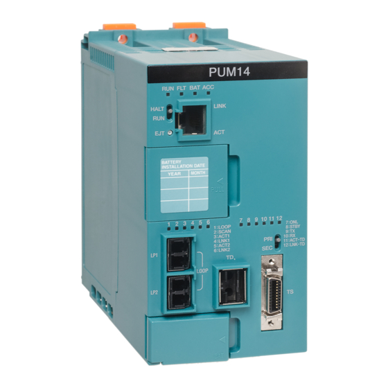
Summarization of Contents
Safety Precautions
Description of Signs
Details the meaning and purpose of various safety signs used in the manual.
Description of Symbols
Explains the meaning and usage of prohibition, instruction, and warning symbols.
Safety Precautions on Installation
Provides essential safety guidelines for installing the device to prevent hazards.
Safety Precautions on Wiring
Outlines critical safety instructions for performing electrical wiring operations.
Safety Precautions on Daily Use
Covers important safety measures for the everyday operation of the equipment.
Safety Precautions on Maintenance and Inspection
Details safety procedures for performing maintenance and inspection tasks.
Safety Precautions on Disposal
Provides guidelines for the safe and environmentally responsible disposal of the product.
Checking Warning Labels
Ensures that warning labels on the main unit are present and legible.
Chapter 1: Overview of T Series Migration
1.1 Overview
Provides a general overview of the T series migration process and its objectives.
1.2 Migration Series and Applicable Controllers
Identifies the T series models and controllers applicable for migration.
1.3 Migration Product List
Lists the specific products involved in the T series migration system.
1.4 Overview of Migration Products
Details the migration products applicable to the T series migration.
1.5 Restrictions and Requirements in T Series Migration
Outlines restrictions and requirements that must be considered during T series migration.
Chapter 2: System Migration Procedures
2.1 T2 Series
Describes the system migration procedures for T2 series controllers.
2.2 S2T/S2E
Details the system migration procedures for S2T/S2E compatible controllers.
2.3 T3 Series
Explains the system migration procedures for T3 series controllers.
Chapter 3: Installation and Wiring
3.1 Installation Condition
Specifies the environmental conditions required for proper installation.
3.2 Before Working
Provides essential checks and preparations before commencing installation work.
3.3 Mounting to Chassis
Describes the correct procedure for mounting the controller unit into a chassis.
3.4 Grounding of Controller Unit and I/O Unit
Details the procedures and importance of proper grounding for system safety.
3.5 Mounting Base Unit
Provides instructions and notes for mounting the base unit BUM7B.
3.6 Power Supply Wiring
Outlines the precautions and procedures for wiring the power supply.
3.7 Mounting/Dismounting Modules
Explains the steps for correctly mounting and dismounting modules on the base unit.
3.8 Mounting/Dismounting Terminal Block Signal Conversion Adapter
Details the procedure for installing and removing the terminal block signal adapter.
3.9 Expansion of Base Unit
Describes how to expand the base unit by connecting expansion units.
3.10 Input/Output Wiring
Provides notes for mounting and wiring I/O modules.
3.11 TC-net I/O Loop Wiring
Explains the procedure for connecting the TC-net I/O loop.
Chapter 4: Start and Stop
4.1 Safety Circuit
Discusses the importance of configuring safety circuits outside the controller.
4.2 Switch Check before Starting
Ensures that operation mode switches are set correctly before system startup.
4.3 How to Start/Stop
Details the correct sequence for powering on and off the controller system.
4.4 LED State at Start
Explains how to check controller module status using status display LEDs.
Chapter 5: Troubleshooting
5.1 Troubleshooting Procedure
Provides a systematic approach to identifying the source of system failures.
5.2 Confirmation of Failure
Guides on how to check status display LEDs and nV-Tool logs for errors.
Chapter 6: Maintenance and Inspection
6.4 Battery Replacement
Details the procedure and importance of regular battery replacement.
6.5 Control Module Replacement
Explains how to replace the controller module, including memory clearing.
6.6 Disposal
Provides instructions for the proper disposal of system components.


Need help?
Do you have a question about the PU224 and is the answer not in the manual?
Questions and answers