
Related Manuals for Neptun ST 1050


Summarization of Contents
Installation of the Built-in Kit
Installation
Details general installation requirements for the built-in kit, including depth below water.
Film Mounting
Instructions for attaching the flat gasket to the built-in pot for film pools.
Mounting the Base Unit
Guidance on selecting a stable site for the pump, ensuring voltage-free and vibration-free mounting.
Mounting of the Inlet Aperture
Explains connecting the air hose to the nozzle frame and securing it with a coil spring.
Technical Data of Pumps
ST 800 and ST 900 Specifications
Provides key technical specifications for the ST 800 and ST 900 pump models.
ST 1050 and ST 1150 Specifications
Lists technical specifications for the ST 1050 and ST 1150 pump models.
Mounting Installation Kit
Installation
Fixing the installation kit 180mm below water surface using threaded nipples for nozzle frame.
Film Mounting
Procedure for attaching the flat gasket to the built-in pot for film pools.
Mounting the Base Unit
Choosing a pump site close to the kit, ensuring voltage/vibration-free mounting on a solid base.
Mounting of the Inlet Aperture
Connecting the air hose to the nozzle frame and installation kit air line connection.
Precautions for Building Companies
Sealing and Component Mounting
Using Teflon tape for plastic threads, ensuring voltage-free and contamination-free assembly.
Pool Use Regulations
Permitted use in pools/ponds only if compliant with local statutory regulations.
Electrical Installation Requirements
Mandatory adherence to rules by licensed electricians, safety devices in power line.
Installation Location and Drainage
Switching device placement, air suction valve/hose above water, adequate floor drain in shaft.
Error / Cause / Repairing
Pump Loudness and Low Power
Troubleshooting loud pump operation and reduced power output due to motor direction or cover.
Pump Not Running or Slow Start
Diagnosing issues related to missing phases or incorrect supply line connections.
Fuse Tripping and Motor Protection
Addressing problems with fuses blowing or motor protection activating due to incorrect settings.
Pool Switching Failure
Resolving issues where the pump cannot be switched from the pool, checking hoses and buttons.
Operating Instructions for the End User
Pump On/Off Control
How to turn the countercurrent pump on and off using the push button.
Stream Direction and Control
Adjusting the all-round swiveling nozzle for stream direction and intensity.
Air Control and Massage
Regulating air supply via the nozzle ring to adjust massage effect.
Swimming Against Countercurrent
Optimal nozzle positioning to create a strong current layer below the water surface.
Massage Equipment Use
Instructions for attaching and detaching the massage unit for optimal effect.
Wintering Procedure
Steps for draining water from the system and pump to prepare for frost.
Parts List - Installation Kit
Built-in Pot Components
Lists items for the installation kit including built-in pot, seal, flange, screws, and protection.
Parts List - Base Unit ST 800
ST 800 Pump and Components
Details parts for the ST 800 base unit, including pump, nozzle frame, console, and fittings.
Parts List - Base Unit ST 900 / ST 1050
ST 900/1050 Pump and Components
Lists components for ST 900 and ST 1050 base units, including pumps, console, and hoses.
Parts List - Base Unit ST 1150
ST 1150 Pump and Components
Details parts for the ST 1150 base unit, covering pump, control box, and various fittings.
Electrical Diagrams
400V Pump Control Box Diagram
Schematic illustration of the 400V pump control box connections and components.
Three-Phase Pump Wiring Diagram
Electrical wiring diagram for connecting a three-phase pump to the system.
230V Pump Wiring Diagram
Electrical wiring diagram for connecting a 230V, 9.8A pump to the system.
Installation Kit Mounting Diagrams
Installation Kit Placement (Fig. 1)
Diagram showing the correct placement of the installation kit 18 cm below the water surface.
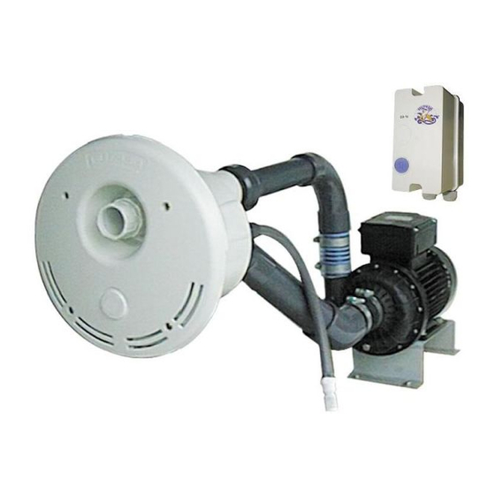
Installation Kit Components (Fig. 2)
Illustration detailing the components of the installation kit and their assembly.
System Connection Diagrams
Air Hose and Switch Connection (Fig. 5)
Close-up view showing the connection of the air hose to the switch mechanism.
System Layout and Level (Fig. 6)
Diagram illustrating the pump, air valve, and PN-hose relative to the water level.
Need help?
Do you have a question about the ST 1050 and is the answer not in the manual?
Questions and answers