
Related Manuals for Swiwin SW120


Summary of Contents for Swiwin SW120
- Page 1 SWIWIN Turbines SW Brushless Series Kero Start Full Autostart with Auto-Restart Operations Manual...
-
Page 2: Table Of Contents
Failsafe ............................6 Ear Protection ............................ 6 Burns ............................6 Turbine Oil ........................7 SWIWIN Limited Lifetime Warranty ....................7 Terms ..........................8 Exclusions ........................8 Operation and Setup .......................... 9 Motor Setup ............................ 12 Introduction........................12 Radio Setup and Training – Learn RC ................13 Servo Tester in Place of a Radio .................. - Page 3 Large font Running Screen ....................18 Main menu – initial screen ......................18 Start Up Screen (advanced functions) ..................... 18 PumpVoltage ........................... 18 RPM StartUp Ramp ........................19 PumpStartUp Ramp ........................19 Pump Auto ............................19 GlowPlug ............................19 GasValve and Fuel Valve ........................ 19 Ignition RPM ..........................
- Page 4 Figure 14 Pump Tube Connection....................13 Figure 15 ECU/GSU ........................16 Figure 16 SW45B ........................... 25 Figure 17 SW60/80B ........................25 Figure 18 SW120/140B ........................26 Figure 19 SW90B ........................... 26 SWIWIN USA Written by CRX Turbines - Andy Fioretti afioretti@crxturbines.com Pg. 4...
-
Page 5: Introduction
Introduction This manual is intended to aid the user in setup and running practices associated with the SWIWIN SW series micro turbines. This manual is not intended to take the place of a primer on micro-turbines. It is assumed that the user has working knowledge and experience with turbines and that each user is familiar with best practices before attempting to run a turbine. -
Page 6: Warning To Bystanders
User accepts full responsibility for all risks including those to any bystanders. User accepts responsibility and bares all risks associated with operation of SWIWIN turbine engines. Warning to Bystanders - User acknowledges the risk of injury or burns to bystanders during start-up or while operating a turbine. -
Page 7: Turbine Oil
1. The warranty is transferable to any subsequent user. There is a $50 admin fee which will be collected when ownership of the motor is transferred. Please make sure that each user registers the motor with SWIWIN at the time of transfer so that service can be maintained on the motor. -
Page 8: Terms
2. SWIWIN will cover labor charges associated with any warranty repair. 3. SWIWIN warranty coverage is limited to replacement of parts and repair of the unit and does not apply to any other losses or damages, consequential or inconsequential to the failure. -
Page 9: Operation And Setup
If the estimate is refused, the turbine will be returned to the user. Owner agrees to cover all return shipping costs. 10. This document constitutes the entire warranty between SWIWIN and the owner and supersedes all prior agreements and/or understandings. - Page 10 Figure 3 ECU Connections and Power Connection Refer to Figure 4 below for steps 3 and 4. 3. Connect one end of the servo cable (provided) between the ECU port labeled “Throttle” and the other end to your receiver #3 input. ...
- Page 11 Figure 4 Engine Connection and Pump Figure 5 ECU Connections Figure 6 Engine Cable Figure 7 Super Trap Pump Figure 8 Throttle Line Figure 9 Battery Power Cable Figure 10 Optional Remote Display Figure 11 GSU Pg. 11...
-
Page 12: Motor Setup
Figure 12 Brushless Pump Figure 13 Motor Setup Motor Setup Introduction – for first time users and for first time use of any engine, it is strongly recommended that the motor be placed into a test stand for the first time. There are a hundred reasons to do this. -
Page 13: Radio Setup And Training - Learn Rc
into whatever apparatus you select. Do not do this indoors. Do route the exhaust outdoors or into a pipe that goes outdoors. Mount the ancillaries neatly where you can see them. Do not skimp on this step. Note the orientation of the parts and the plumbing. Make sure the valve is off. -
Page 14: Servo Tester In Place Of A Radio
should be at minimum now. Press Ok to lock in the “minimum” value. Servo Tester in Place of a Radio For test purposes, a servo tester can be used in place of a radio. The use of a servo tester provides a means to isolate the motor especially if there are any suspected radio issues. -
Page 15: Ignition
the radio. 4. Turn on the fuel valve. 5. Raise the trim to 100% and observe ECU status switches from stop to “ready”. If the ECU does not transition to ready state, recheck the ECU to radio connection and retrain if needed. 6. -
Page 16: Shutdown Procedure
5. Turn off power to the controller 6. Turn off power to your radio The SWIWIN ECU was designed from the ground up and is based on 32 bit microprocessor functionality and designed specifically for SWIWIN Turbines. Figure 15 ECU/GSU The ECU offers the following benefits: Pg. -
Page 17: Ecu/Motor Electrical Connections
Data Logging Auto start Automatic Restart Color Screen visible in direct sunlight Configurable thrust curve with very fast throttle response ECU/Motor Electrical Connections Do not exceed these voltages! Receiver voltage:5-8.4V(5S Nimh or 2S Life or 2S Lipo) Power voltage:9.9-11.1V (3S Life or 3S Lipo) GSU Screen Button Function “OK”... -
Page 18: Large Font Running Screen
4300/1000 = 4.3 volts RC – throttle position from 0 – 100% Large font Running Screen Press “C” to toggle between large screen and normal Main menu – initial screen From the initial screen, press “OK” key, click “C” to toggle back to boot screen StartUp –... -
Page 19: Rpm Startup Ramp
Each pump is different even for the same brand of pump. .2 - .8 is a huge change. Make adjustments .02 - .04 increments at a time. RPM StartUp Ramp – Set ramp profile – On new engines please follow the default parameters. -
Page 20: Preheat Rpm
phase commences Preheat RPM – Set the RPM value for preheat phase to begin. RPM Starter Off – Set the RPM where the starter motor will disengage. Learn RC This menu is to train the transmitter to the ECU. Be sure to depress OK to lock in the value that you select. -
Page 21: Running Display
Running Display This menu control running parameters RPM ACC – Press “OK” to access acceleration curve Max RPM – Set maximum RPM Idle – set idle RPM Min RPM – set stop RPM - if motor RPM falls below this setting, motor will shutdown. -
Page 22: Test Function Menu
conservative with adjustments to the response curve. Test function menu Press “OK” to access test functions Test Pump – depress OK and hold OK to increase pump speed. Pump increases gradually. Test pump initiates fuel solenoids simultaneously. Be careful not to flood the engine. -
Page 23: Data Chart
Data chart Record running data use the increment and decrement key to step through events in the data chart. color corresponding each parameter as follows Red – Temp Yellow – Throttle position light blue – Pump Green – RPM Dark Blue - Power Pg. -
Page 24: Ecu Parameters - Brushless Starter
ECU Parameters – Brushless starter Auto Restart ECU Parameters – Parameters may vary dependent on firmware release Menu Parameter SW60 SW120/140 SW180/210 Startup Pump voltage RpmStartup ramp Pump startup ramp Pump auto Glowplug 6.4-6.8 6.4-6.8 Gas valve 40-20 40-20 40-20 Ignition rpm 6000 5000... -
Page 25: Engine Diagrams
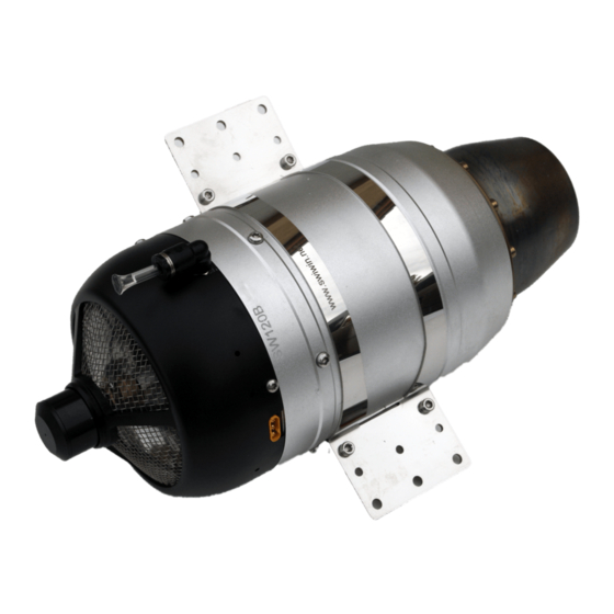
Engine Diagrams Figure 16 SW45B Figure 17 SW60/80B Pg. 25... - Page 26 Figure 18 SW120/140B Figure 19 SW190B Pg. 26...
-
Page 27: Specifications
Specifications SW60B SW80B SW120B SW140B SW170B SW190B Diameter 84mm 84mm 100mm 100mm 110mm 110mm Length 203mm 203mm 250mm 250mm 258mm 258mm Weight 783g 788g 1255g 1255g 1457g 1563g RPM range 50,000-160,000 50,000-155,000 38,000-125,000 38,000-128,000 36,000-110,000 36,000-115,000 Thrust 120N 140N 170N 190N 650℃... - Page 28 INDEX Cooling ............19 Introduction ..........4 Data chart ..........22 Learn RC ........... 19 Main menu – initial screen ......17 Ear Protection ..........5 ECU ............15 Operation ............. 8 ECU Operation .......... 15 RPM Acceleration Curve/Delay time ..20 ECU Parameters ........
Need help?
Do you have a question about the SW120 and is the answer not in the manual?
Questions and answers