Table of Contents
Advertisement
Quick Links
Advertisement
Table of Contents
Troubleshooting

Related Manuals for Tidel TR300 Series


Summary of Contents for Tidel TR300 Series
- Page 1 TR Series Recyclers Service Manual 450-0461-001 Rev. F...
- Page 2 License Agreement You have acquired a device (TR250 Series) that includes software licensed by Tidel Engineering from Microsoft Licensing Inc. or its affiliates ("MS"). Those installed software products of MS origin, as well as associated media, printed materials, and "online" or electronic documentation ("Windows 8"), are protected by international intellectual property laws and treaties.
- Page 3 Contents License Agreement Preventive Maintenance Serial Number Information General Information Component Location Electronics Bay Access Specifications/Installation Initial Setup Menu Definitions Error Messages TR250 Cash Handler Components TR253 Coin Handler Components Coin Hoppers Coin Sorter Combination Locks Network Communication 10-1 Note Recycler 11-1 Printers 12-1...
- Page 4 Preventive Maintenance is required for all Tidel TR250 Series Products. Preventive Maintenance must be performed by Tidel Certified Technicians. Tidel is not liable for charges resulting from Preventive Maintenance, repairs due to lack of Preventive Maintenance or terms and obligations of Service Plans by any other entity than Tidel.
- Page 5 2 = Glory ci200 Note Handler 3 = Glory ci300 Note Handler 5 = Glory ci50 Note Handler 7 = TR Series Note Handler w/Fujitsu G750 Note Recycler B = BCR Coin Handler (5 Hopper utility with 1 reject bin) R = Rolled Coin Dispenser...
- Page 6 Serial Numbers begin with 3 characters followed by 5 numbers Tidel TR250 Series (Note Handler), equipped with a Fujitsu G750 Note Recycler The Serial Number decal can be found at the top of the display or inside the Electronics Bay of the Note Handler Vault, on the left side wall.
- Page 7 Coin Handler Serial Number Prefixes Serial Numbers begin with 3 characters followed by 5 numbers Tidel TR253 (Coin Handler), equipped with a Glory Mach 6 Coin Sorter and (5) Coin Hoppers - Plus (1) Reject Hopper. Power is be supplied by Tidel Note Handler (N7F serial number types)
- Page 8 Coin Handler Serial Number Prefixes Serial Numbers begin with 3 characters followed by 5 numbers Tidel Rolled Coin Dispenser. Equipped with a self contained Power Supply Paired with TR 250 Series Note Handlers. Tidel Rolled Coin Dispenser. Equipped with a self contained Power Supply Paired with Glory Note Recyclers.
- Page 9 R50 model: Tidel Note Handler (early TR Series) equipped with Fujitsu G750 Note Recylcer, Glory Mach 6 Coin Sorter and (5) Coin Hoppers. S5 model: Tidel Note Handler (early TR Series) with Fujitsu G750 Note Recylcer only (no Coin Handler),...
- Page 10 „ Placing the ON/OFF Switch in the OFF position IS NOT suffcient to prevent electrical shock or injury !!!! When there is a problem of any nature with Tidel Equipment, perform a power reset „ „ then attempt the function again.
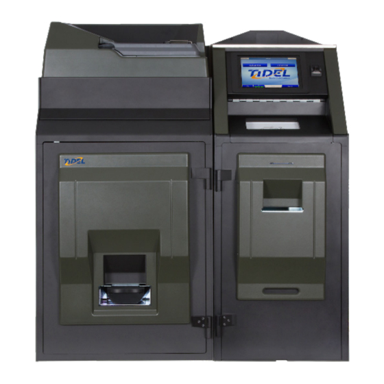
- Page 11 Component Location - Front View TR250 Coin Handler with TR253 Coin Handler Coin Sorter Loading Tray Register Drawer/NFC Scanner Operation Monitor / Touchscreen Finger Print Reader i-Key Reader/Socket USB Port Note Collection Door Printer Receipt Ejection Slot Foreign Article Reject Tray 10) Bill Recycler Vault Door Access Cover 11) Courier Tray/Drop Slot 12) Coin Sorter Top Cover...
- Page 12 TR250 Electronics Bay Access The Electronics Bay contains the Control PC and Power Supplies. The Electronics Bay must be opened to service the following: Display/Touchscreen assembly Fingerprint Scanner NFC Scanner (Register Till Scanner) Speakers Rear connections Raise the Electronics Bay Lid Pivot the Display/Touchscreen assembly forward to the service position Place a protective pad here when servicing...
- Page 13 TR250 Note Handler Components Printer Foreign Atricle Reject Tray Combination Lock Note Handler Vault Handle Drop/Courier Tray Insertion Slot Drop/Courier Tray Cassette Rack Release Lever Note Recycler Release Lever...
- Page 14 TR253 Coin Handler Components Combination Lock Coin Vault Door Handle Coin Collection Tray Coin Collection Tray Rack Overflow Bin Coin Hoppers...
- Page 15 TR253 Coin Handler Components Power Supply Coin Sorter Top Cover Sensor Hardware Support PCB...
- Page 16 Notes...
- Page 17 Tidel Series Recyclers Installation 450-0457-001 Rev. C...
- Page 18 Cash Handler Specifications Cash Handler Cabinet Dimensions: Depth: 36.19” (919 mm) 2” space suggested behind the unit for cabling Width: 19” (483 mm) Height: 44.25” (1242 mm) 49” (1245 mm) with NFC 60.5” (1537 mm) with Maintenance Access Cover open Weight: 878 lbs (398 kg)
- Page 19 Coin Handler Specifications Coin Handler Cabinet Dimensions: Depth: 2” space suggested behind the unit for cabling 36.19” (919 mm) Width: 25” (635 mm) Height: 49.5” (1257 mm) Height 64” (1626 mm) Cover lifted Weight: 854 lbs (387 kg) Front Clearance - 31” from front of Coin Handler Vault for full Coin Hopper Rack extension. Total Depth Clearance - 67”...
- Page 20 TR250 Series With Cash and Coin Handling Cash Handler Cabinet Dimensions: Depth: 36.19” (919 mm) 2” space suggested behind the unit for cabling Width: 19” (483 mm) Height: 44.25” (1242 mm) 49” (1245 mm) with NFC 60.5” (1537 mm) with Maintenance Access Cover open Weight: 878 lbs (398 kg)
- Page 21 Tidel equipment to the floor. When the Tidel equipment is secured to this type of floor, with the above mentioned anchors, bolts and washers, it will require at least 6,000 pounds of vertical pressure or 8,420 pounds of horizontal pressure, per anchor, to forcibly remove the anchors from the floor.
- Page 22 Step 5: Anchors must be “set” before installing the bolts. To set the anchors, Tidel recommends using an approved “Setting Tool” to drive the plug inside the anchor down with a hammer until it is wedged solidly in the floor.
- Page 23 Report freight damage to the Tidel Shipping Department at 1-800-678-7577, ext 1152. Bolt Down Preparation Ensure the bolt down location surface is level and meets the required clearances before removing the TR250 Series components from the pallet(s). Open the vault and locate the “Bolt Down Template”...
- Page 24 TR250 Bolt Down Step 1: Prior to placing the TR250 into the bolt down location, remove the L-Brackets from the rear of the cabinet. (Place them inside the Note Handler, under the Recycler when install is done). Do Not use the Vault Door as leverage to place the cabinet over the anchors ! Step 2: Place the TR250 into the bolt down area (alignment of the anchors/bolt holes will be performed later).
- Page 25 Preparing the Note Recycler for operation Step 1: Using a JIS Screwdriver, remove the (2) screws “A” that secure the Cassette Rack Shipping Bracket to the rear of the Cradle (do not discard bracket or screws). Step 2: Using a JIS Screwdriver, remove the (3) phillips head screws that secure the Upper Rack Rail bracket “B”...
- Page 26 Step 4: Pull the Note Recycler Assembly release lever forward and allow the Note Recycler to extend from the Cradle approximately 18 inches. Rear View of Note Recycler Step 5: Remove the shipping bracket from the rear of the Cassette Rack “A”...
- Page 27 Step 7: Press the top of the Cassette Rack Release lever and pull the Cassette Rack fully out. Upper Transport Release Lever DO NOT DISTURB Cassette Rack Release Lever Step 8: Using a JIS Screwdriver, remove the Cassette shipping brackets “E”...
- Page 28 Prior to securing the TR250 to the floor If a Coin Handler is being installed with the TR250: X Perform placement and bolt down procedures for the Coin Handler prior to installing the securing bolts into the anchors See pages 1-14 through 1-18 X After the both cabinets are in place and aligned, install the securing bolts into the an- chors X Connect any network cables, power cords or ground wiring to the appropriate con-...
- Page 29 Note Recycler Assembly Installation Step 1: Position the Note Recycler assembly back into the cabinet opening and route the wiring harness into the electronics bay. X To ease installing the Note Recycler - extend the Cassette Rack and press down to leverage the rear of the Dispenser UP WARNING - Ensure the Note Recycler is seated fully into the R50 cabinet Place a Cradle Retaining Bracket (“C”) and ensure the anchor mounting hole and...
- Page 30 Removing the Coin Handler from the Shipping Pallet Tidel recommends lifting/moving duties be performed by a minimum of (2) persons Things to consider before proceeding: Removal from the shipping pallet may cause the unit to drop slightly, resulting in damage to flooring - protection such as a sheet of plywood can help reduce the risk of damage.
- Page 31 Coin Handler Placement Step 1: Prior to placing the Coin Handler into the bolt down location, remove the L-Brackets from the rear of the cabinet and apply the foam weatherstripping to the right side edges of the cabinet. Place the bracket inside, at the bottom, of the Coin Handler when installation is done. Step 2: Move the Coin Handler into the bolt down location (left side of the TR250 Cash Handler).
- Page 32 Coin Handler Bolt Down Step 1: Connect the Coin Handler wiring harness to the terminals at the top/rear of the TR250 Cash Handler cabinet. a) Cable length will determine orientation of connections. b) Connect the ground wire to the center phillips head screw on the Power Supply Chassis. c) Secure the wiring harness to the TR250 strain relief plate using the tie wraps included in the accessory kit.
- Page 33 Initial Start Up/Getting Started Power Up Sequence If a Coin Handler is paired with the Note Handler and is equipped with a UPS device: Hold the On/Off button on the UPS until (2) beeps are heard (UPS should be ON). Press the ON/OFF button at the top/left rear of the unit (facing unit) - The “white”...
- Page 34 Functional verification Coin Collection Tray - Rack Step 1: Navigate to the Door Solenoid and Sensor Maintenance Menu: Log In > Done > (1-2-3-4-5-6) > Maintenance Menu > Door Solenoids and Sensors a) The displayed Sensor map should indicate the Coin Tray Inserted.
- Page 35 Functional verification Coin Handler Top Cover Step 1: Open the Coin Handler Top Cover. The displayed Sensor map should indicate the sensor is are OPEN. Step 2: Close the top cover on the Coin Handler The displayed Sensor map should indicate the Top Cover Sensor is CLOSED. Coin Sorter Step 1: Navigate to the Sorter Maintenance Menu: Log In >...
- Page 36 Functional verification Network Connection Step 1: Ensure the network cable extiting the TR Series product is connected to the desired hub/ switch/router socket. Step 2: Navigate to the Network Configuration Menu: Log In > Done > (1-2-3-4-5-6) > Maintenance Menu > Network Step 3: Select PING Google.
- Page 37 Tidel TR250 Series Initial Setup Guide 450-0460-001 Rev. B...
- Page 38 License Agreement You have acquired a device (TR250 Series) that includes software licensed by Tidel Engineering from Microsoft Licensing Inc. or its affiliates ("MS"). Those installed software products of MS origin, as well as associated media, printed materials, and "online" or electronic documentation ("Windows 8"), are protected by international intellectual property laws and treaties.
- Page 39 Initial Setup License Agreement Before You Start Component Location Printer Combination Lock Initial Start-Up General Information Mandatory Programming 2-10 Till Check In/Out Setup Overview 2-12 Department ~ Register Relations 2-13 Creating Departments 2-16 Creating Registers 2-17 Linking Registers To Departments 2-18 Creating Mixes 2-19...
- Page 40 Before You Start Prior to performing an initial start-up, insure the following are available: Note Recycler Cassette Keys When shipped from the factory, the keys are secured to the front of the Note Recycler Frame (above and to the left of the Cassette Rack) ...
- Page 41 Component Location - Front View TR250 Note Handler with TR253 Coin Handler Coin Sorter Loading Tray Register Drawer / NFC Scanner Operation Monitor / Touchscreen Finger Print Reader i-Key Reader Note Collection Door Printer Receipt Ejection Slot Foreign Article Reject Tray Bill Recycler Vault Door Access Cover 10) Courier Tray/Drop Slot 11) Coin Sorter Top Cover...
- Page 42 Tidel TR250 Note Handler Components Printer Foreign Object Reject Tray Combination Lock Note Handler Vault Handle Drop/Courier Tray Insertion Slot Drop/Courier Tray Cassette Recycler Release Lever Recycler Release Lever...
- Page 43 TR253 Coin Handler Components Coin Loading Tray Combination Lock Coin Vault Door Handle Coin Collection Tray Coin Collection Tray Rack Overflow Bin Coin Hoppers...
- Page 44 Built In Printer Paper Door Release Lever Step 1: Press down on the paper door release lever to expose the paper tray. Step 2: Pull enough paper off the roll to extend out of the paper tray and place the paper into the tray so the paper comes off the top off the roll.
- Page 45 Combination Locks Opening the door for the first time From the factory, the default combination is 1-2-3-4-5-6. a) Enter 1-2-3-4-5-6 on the keypad and rotate the dial to unlock and open the door. To change the default combination Step 1: Enter six zero’s. The lock will beep TWO times.
- Page 46 Default Set-up (USA) When the TR250 Series units are shipped from Tidel, the default Log In code is set to 1-2-3-4-5-6. Tidel recommends the default code be changed AFTER the initial setup of the TR250 Series units has been completed.
- Page 47 General Information Menu Navigation This Operator’s Manual will guide you through typical setup and operation procedures. Menu maps will indicate “target” menu selections. If the “target” menu selection does not appear on the current screen, select until >>> the desired menu selection is displayed. EXAMPLE: If the actual path is: Log In...
- Page 48 Location and User Import If the Location Department/Register and User/Group associations are being imported from the “Tidel Import” spreadsheet, perform that function prior to setting any site specific information. Log In > Done > (1-2-3-4-5-6) > Configuration > Restore From Back Up...
- Page 49 Mandatory Programming Note Handler Serial Number The Note Handler Serial Number should be set from the factory, however, verification is recommended. Log In > Done > (1-2-3-4-5-6) > Configuration > Edit Configuration > Note Recycler Serial # The Serial Number of the Note Handler can be found on the Manufacturers decal on the inside/left wall of the Electronics Bay Coin Handler Serial Number The Coin Handler Serial Number IS NOT SET FROM THE FACTORY and must be entered at the time...
- Page 50 Till Check In/Out Operation Setup There are 3 aspects of the “Check In/Out” process to consider prior to begining. Users are grouped by the functions they are allowed to perform Registers are grouped into Departments User Groups are assigned to Departments containing the Registers they can access Initial setup is accomplished by: Create the Department/Register/Mix relation Departments...
- Page 51 Department ~ Register Relations 2-13...
- Page 52 Notes on Department/Register/Mix Setup DEPARTMENTS typically contain a group of Registers. User groups are linked to DEPARTMENTS and all Users in the User Group can dispense or deposit tills linked to the Registers in the DEPARTMENT. Users linked to the DEPARTMENT can perform dispense/deposit activity for all Registers within the DEPARTMENT.
- Page 53 Dept Register Schedule 1 CasinoDept C-WeekDay Front Cashier C-Weekend Back Cashier 2 FoodDept Breakfast Buffet Lunch BBQ Pit Supper Lobby Bar Pool Bar Alcohol 3 HotelDept Cigar-Bottle Check In Registration Amenities Gift Shop 2-15...
- Page 54 Creating Departments Registers are grouped into DEPARTMENTS Users linked to the Department can access all Registers within the Department To create a DEPARTMENT: Log In > Configuration Menu > Edit Groups, Mixes > Edit Departments Department Contains Departments Registers Registers Casino Dept Food Dept Hotel Dept...
- Page 55 Creating Registers REGISTERS are assigned to Departments. A Register can be assigned to multiple Departments. To create a REGISTER: Log In > Configuration Menu > Edit Groups, Mixes > Edit Registers Department Departments Registers contains Registers Back Cash Casino Dept BBQ Pit Hotel Dept Buffet...
- Page 56 Linking Registers To Departments To assign REGISTERS to DEPARTMENTS: Log In > Configuration Menu > Edit Groups, Mixes > Departments Department Registers Departments contains Registers Casino Dept Back Cash Food Dept BBQ Pit Hotel Dept Buffet Check In Cigar-Bottle << Front Cash Gift Shop Lobby Bar...
- Page 57 Creating Mixes MIXES are pre-determined dispense amounts. A MIX determines the amount and type of currencies to be dispensed at the start of the shift. MIXES are assigned to Registers. Multiple Mixes can be assigned to a specified Register. To create a MIX: Log In >...
- Page 58 Dispense Amount Selections (Mix) Name Use the virtual keyboard on the Touchscreen to enter the User name. CAPS LOCK SHIFT will toggle between Upper/Lower Case and Numeric/Symbol characters. Edit Money Select the GREEN BOX to the right of the Currency type first. Use the “pop-up”...
- Page 59 Linking Mixes To A Register To link a MIX to a REGISTER: Log In > Configuration Menu > Edit Users, Groups > Edit Mixes/Mix Schedules and Relationships Note: Multiple Mixes can be linked to a specific Register. Link Mixes to the Select the Register selected Register Back Cash...
- Page 60 Dispense Mix Schedule Options Structured “SCHEDULES”, can be programmed to limit dispense time periods. A dispense schedule must be assigned to a MIX. The following options are available for limiting MIX dispense periods TYPE Schedule Setting Options All Day Every Day Mix can be dispensed anytime - no restrictions Range Can be set to dispense only during set begin and end time range...
- Page 61 Programming Mix Schedules To create a SCHEDULE: Log In > Edit Users, Groups > Edit Mixes/Mix Schedules and Relationships Mixes Mix contains Mix Schedules Mix Schedules Alcohol Amenities C-Weekday C-Weekend Food AM Food MID Food PM Registration Edit Delete Edit Delete Edit Users can a select schedule type and dispense time settings...
- Page 62 Linking Schedules To A Mix To link a SCHEDULE to a MIX: Log In > Configuration Menu > Edit Mixes/Mix Schedules and Relationships Note: Multiple Schedules can be linked to a Mix. Select a SCHEDULE Select the MIX to link with the MIX Alcohol Amenities C-Weekday...
- Page 63 Permission Level ~ User Relations 2-25...
- Page 64 Notes On User Setup PERMISSION LEVEL determines which functions can be perform by a group of Users. A PERMISSION LEVEL must be assigned to a User Group and applies to all Users in the group. Only (1) PERMISSION LEVEL can be assigned to a User Group USER GROUP is a collection of Users that share the same restrictions/allowances of operational functionality.
- Page 65 Permission User Group User Name Level Resort Mgr Officers Director Level Loss Prevent 1 Casino Managers Casino Mgr Food Mgr Manager Level 2 Food Managers Hotel Mgr 3 Hotel Managers Casino Cashiers C-Cashier Names F-Cashier Names Food Cashiers Cashier Level H-Cashier Names Hotel Cashiers Global Level...
- Page 66 User Log In Options Users can “Log In” using several methods, depending on settings and equipment configuration. Log In methods are typically set when users are added, but can be modified using the following processes. i-Key Entry NOTE: The TR250 must be equipped with an “i-Key” reader to utilize this functionality Log In >...
- Page 67 User Log In Options Touchscreen Entry NOTE: Users must enter a “Logon ID” “Logon PIN” and a in order to access the TR250 functions. The ID and PIN numbers are assigned at the time the User is entered into the system. User only Log In (using ID and PIN number) The User can enter their assigned “LOGON ID”...
- Page 68 Creating A Permissions Level A PERMISSION LEVEL is created to determine the functions and restrictions that apply to ALL Users within the Group. To create a PERMISSION LEVEL: Log In > Configuration Menu > Edit Groups, Mixes > Groups & Relationships Act for others Cashier Level Can Deposit Till...
- Page 69 Authorize PACN When accessing menus for service, a technician’s access may require PIN entry by a User. Users with the authority to allow a Service Technician access to the TR Series should be linked to Groups with this permission.. Buy change A “buy change”...
- Page 70 Permission Definitions Cold Start and Restore A User with the ability to Cold Start the Note Handler can erase all Users and operational setup. A “Restore” can install users and operational setup from a USB stick to the Note Handler operating system.
- Page 71 Exchange A User can adjust the note count in the Note Cassettes. Exit Software If allowed, the User can exit the Tidel Application screen and access the Windows Operating System. Forego remedial videos Error remedy videos will not be displayed to a User with this option assigned.
- Page 72 Permission Definitions Open Doors Allows the User to open doors specified in the Group or Individual Permissions. Open Drop Chute Allows the User to open a locked Drop Deposit Chute. The User must also have the permission “Open Doors” enabled in order to open specific doors. (Only on units equipped with Storage/Drop vaults).
- Page 73 Permission Definitions Service Recyclers When enabled, the User can access Note Recycler menu from the Status Bar (after Log In), to perform functions such as clearing errors, manually loading cash, auditing funds, etc. Use Courier Tray Provides access to menus which allows funds to be moved to a Courier Tray for pickup by armored car services.
- Page 74 Creating A User Group Departments/Registers are linked to the User Groups. Users can only access Registers contained within the Departments linked to their assigned USER GROUP. To create a USER GROUP: Log In > Configuration Menu > Edit Groups, Mixes > Groups & Relationships Group Contains Departments Groups...
- Page 75 Linking A Permission Level To A User Group The Permission Level is typically assigned at the time User Group is created. A NEW Permission Level cannot be created by following this process (See “To Create A Permission Level” in this manual). To assign or change the Permission Level assigned to a User Group: Log In >...
- Page 76 Adding Users When a USER is added, prompts to enter Log In information must be completed in order to save the User in the system. Log In requirements are dependent on the TR250 equipment settings and configuration. (Please see the USER LOG IN OPTIONS IN THIS MANUAL) After adding a User, the User is typically assigned to a Group, which determines which Departments/Registers can be accessed.
- Page 77 User Settings Will appear as the second half of the User Name. Last Name Will appear as the first half of the User Name. First Name Required to Log In (1-12 numbers). Logon ID Additional Log In (1-8 numbers). Required for Log In - must be entered Logon PIN at the time the User is added.
- Page 78 Adding Users to a User Group After adding Users, User must be assigned to a Group, which determines which Departments/ Registers can be accessed. To add a USER: Log In > User Management > Add User To Group Add User Modify User Delete User Add User To Group...
- Page 79 Linking Departments To User Groups Linking a Department to a User Group allows Users within the Group to check in/check out registers that are grouped in the Department To Link a Department to a User Group: Log In > Configuration Menu > Edit Groups, Mixes > Groups & Relationships Food Dept Casino Dept Casino Cashiers...
- Page 80 Opening Doors Opening a door can be accomplished by using EITHER of the 2 methods listed below. Combination Lock method: From the factory, the default combination is 1-2-3-4-5-6 this combination may have been changed at installation/start-up. a) Enter the current combination on the keypad and rotate the entire dial (clockwise), to the unlock the door.
- Page 81 Loading Note Recycler Cassettes (Manually) Step 1: Open the Note Recycler Door. Step 2: Press the TOP half of the Release Lever to extended the Cassette Rack. Cassette Rack Front Step 3: Remove the Cassettes. Step 4: Unlock the Cassette and open the Cassette Door. Step 5: Retract the Packer Plate.
- Page 82 Note Recycler Manual Cassette Count Entry If notes were placed into the Recycle Cassettes Manually, the Cassette count must be entered manually. If Cassette denominations were changed from the default settings, Cassette denominations can be re-assigned in this menu. Check the Cassette denomination setup: Log In >...
- Page 83 Loading Note Recycler Cassettes (Using Note Recycler) Notes that are added using this method will be deposited in the recycling cassettes for future dispensing. Cassette Counts will automatically be adjusted to reflect the notes added. To insert notes using the Note Recycler: Log In >...
- Page 84 Manually Adjusting Coin Counts To correct or modify the coin count in the Hoppers: Log In > Status (bottom tool bar) > Coin Recycler > Coin Exchange Denomination Original Count New Count Select the count to adjust $0.01 Tap Done when complete $0.05 Adjust by 100 $0.10...
- Page 85 Main Screen Functions 1.00.12598.0 02/06/18 02:33 PM TR250 Cash Management End Of Shift Start Of Shift Status Help Log In System Notes Coins Allows dispensing pre-determined amounts based on departments and Start Of Shift cash registers (register check-out). When selected, the User will be prompted to Log In. Depending on operational settings...
- Page 86 Main Screen Functions 1.00.12598.0 02/6/18 02:33 PM TR250 Cash Management Start Of Shift End Of Shift Status Help Log In Notes Coins System Allows Users to deposit cash collected during the shift (register check-in). End Of Shift When selected, the User will be prompted to Log In. Depending on operational settings...
- Page 87 Main Screen Functions 1.00.12598.0 02/06/18 02:33 PM TR250 Cash Management Start Of Shift End Of Shift Status Help Log In Notes Coins System Help Contains a menu of items concerning the operation of the TR250 LOG IN provides access to setup, operational, reporting and maintenance Log In menus.
- Page 88 Status Screen Indications Selecting “STATUS” while the Main Screen is displayed (no User logged in), will present a current conditions screen. No corrective action can be performed from this screen Tidel TR250 Status 1.1.0.0 SN: TF01000 Device: Acceptor: Dispenser: Error Code: NONE...
- Page 89 Status Screen Menus after Log In Selecting “STATUS” (bottom of screen), will allow access to menus which can perform corrective functions. Tidel TR250 Status 1.1.0.0 SN: TF01000 Device: Acceptor: Dispenser: Error Code: NONE Coin Recycler Hopper 1 Hopper 2 Hopper 3...
- Page 90 Clearing Note Recycler Errors Clear Jam/Error Selecting this item will display an illustrated view of the problem area. Note Exchange Required Fix Problem Fix Problem Prompts for error resolution or a service video (if available), will assist Users with troubleshooting and correction procedures. Typical errors are due to Cassettes manipulated by removal/replacement or jams on the Note Feed Path (transport).
- Page 91 Clearing Coin Recycler Errors Clear Error Selecting this item will display an illustrated view of the problem area. Coin Hopper Not Communicating Fix Problem Fix Problem Prompts for error resolution or a service video (if available), will assist Users with troubleshooting and correction procedures.
- Page 92 2025 W. Belt Line Rd, #114 Carrollton TX 75006 1-800-678-7577 (phone) 972-484-1014 (fax) techserv@tidel.com 2-54...
- Page 93 TR Series Recyclers Menu Definitions...
- Page 94 Users which will override Group Permissions. If no Individual User Permissions are assigned to a User, the Group Permissions will apply. Logging onto the TR Series Menus: From the Main Screen, select Log In Depending on operational settings...
- Page 95 When an End Of Shift (Register Check In), is performed by a User with the ACT FOR OTHERS ability: If the TR Series Till Tracking is set to “NFC or Till ID” mode: X Dept/Register can be selected from a displayed list...
- Page 96 Act For Other Exclusions Log In > Configuration Menu > Edit Groups, Mixes, etc > Can Act For Others Exclusions When Users are allowed to “Act For Others” (check in another person’s checked out till), this function can be used to specify which Groups (and departments/registers associated with the Group) are excluded from being checked in by “Act For Others”...
- Page 97 Add User To Group Log In > User Management This function assigns individual Users to a Permission Group that share the same abilities. Users can be assigned to more than one Permission Group. Advance Cash (operation) Log In > Advance Cash This function is performed when a register is checked out (being used), but requires cash due to low funds (typically due to lottery payouts, check cashing, refunds, etc...) Any amounts dispensed will be added to the Register’s balance.
- Page 98 Start New Accounting Period is performed. b) End Accounting Period is performed. If “Auto Start OF Day Time” is assigned, the TR Series Recycler will automatically assign the date/time as the name of the file when the new START OF DAY begins.
- Page 99 Allow Multiple Tills Per Register (T/F) Log In > Configuration Menu > Edit Configuration > EOD and Accounting Options Allows Users to start a shift (register/till check out), and associate the till check out to a register that currently has a checked out till assigned to it. Useful when a User is starting a shift before the current User has end their shift.
- Page 100 Log In > Configuration Menu > Edit Groups, Mixes, etc > Permission Groups > (Select Group) When the TR Series is in an OFFLINE mode, Users in a group with this permission assigned can still log in and perform functions.
- Page 101 When accessing menus using a PACN code, a technician’s access may require PIN entry by a location User (depending on TR Series Recycler Settings). Those location Users must belong to a Permission Group with this “Can Authorize PACN” assignment.
- Page 102 Selecting OFF in this menu will disable the existing auto start time. If “Used Named Accounting Period” is enabled, the TR Series Recycler will automatically assign the date/time as the name of the file when the new START OF DAY begins.
- Page 103 Browse And Search For Dept/Register Log In > Configuration Menu > Edit Configuration > User Interface This function provides the user a way to search for departments or registers when editing the Department ~ Register relationship ENABLED: When more Departments or Registers exist than can be displayed in the Edit menu, a “keyboard” will be available in the Edit Groups, Mixes >...
- Page 104 Cash Advance Log In > Cash Advance This function is performed when a register is checked out (being used), but requires cash due to low funds (typically due to making change, lottery payouts, check cashing, refunds, etc...) The User will be prompted to select the Department/Register the advance is associated with. When an End Of Shift is performed, any “advanced”...
- Page 105 Cash Out (operation) Log In > Configuration Menu > Edit Groups, Mixes, etc > Permission Groups > (Select Group) A Start Of Shift is not required to dispense cash using this function. Allows coins or notes to be dispensed without associating a register or department. When selected, the user will be prompted to select the denomination type and number of coins/ notes to dispense.
- Page 106 Log In > Configuration Menu > Edit Configuration > Device Configuration > Coin Recycler Configuration > Coin Acceptor Used to set the type of Coin Sorter being used with the TR Series Recycler. Mach 6 = TR Series default type Coin Sorter.
- Page 107 Coin Recycler Log In > Status > Coin Recycler Audit (Coins) A User must remove the Coin Hoppers from the Coin Handler, remove the coins from the Hopper and process them through the Coin Sorter to verify amounts. Coin Exchange From this menu, the coin count in the Hoppers can be altered.
- Page 108 Provides access to the Coin Handler Setup: X LAN Connection Local = Coin Handler is connected directly to the TR Series computer. No Device = TR Series will not contain any coin recycling menus. Simulator = Allows the manufacturer to perform testing when a Coin Recycler is not actually connected to the TR Series (not for field use).
- Page 109 Coins Out Log In > Status (bottom tool bar) > Coin Recycler > Dump/Accept > Coins Out Performing a “dump” (coins out), will produce a report indicating the beginning counts, ending counts and the “coin out/coin in” net difference . Coins dumped using this feature do not effect Register or Overflow Bin amounts.
- Page 110 Cold Start Configuration Log In > Configuration Menu > Edit Configuration > Cold Start Configuration This function will clear the operational parameters and hardware setup of the TR Series. User information and report history will not be cleared. Cold Start Database Log In >...
- Page 111 Configure Cash 360 model Log In > Configuration Menu > Edit Configuration > Courier Options This is enabled for customers that perform change ordering/deivery operations. In order for this feature to function: a) Cash 360 must be enabled b) External Vault fund must be enabled c) Funds must exist in the External Vault Fund ENABLED: Functions for delivering ordering/delivering change will be available.
- Page 112 Configure FiServe CorPoint Reporting Log In > Configuration Menu > Edit Configuration > Courier Options Customers utilizing FiServ’s Corpoint web based reporting will be required to populate the appropriate fields/parameters (designated by FiServ/Host). Allows FTP setting to be configured. Used for sending XML transaction files Fiserv Corpoint Interface (Enable/Disable) Enabled when customers utilize Fiserv Corpoint for provisional credit operations.
- Page 113 When enabled, PDF file copies of reports will be email when an End Of Day is performed. Garda Serial Number A customer specific/unique Serial number can be entered here. This is not the Tidel manufacturing Serial Number. SMTP Server IP Address The Host Server IP address where emails will be sent. Send Email To The email address where PDF files will be sent.
- Page 114 Copy Installation Files Log In > Maintenance Menu If a flash drive containing TR Series operational setup files is inserted into a USB port, the setup information can be transferred to the TR Series. This function will not import User/Permission Group/Department/Register or Mix information (see IMPORT SPREADSHEET or RESTORE FROM BACKUP).
- Page 115 Correct Drop Log In > Correct Drop Allows Users to make adjustments to the drop amounts AFTER an “Empty Drops” has been performed. If drops currently exist in the Drop Vault, this menu items will be subdued. Correct Vault Drop Log In >...
- Page 116 Courier Options Log In > Configuration Menu > Edit Configuration > Courier Options The following sub menus can be accessed: X Allow Other Items In Courier Tray (T/F) X Bank Owns External Vault Fund (T/F) X Configure Cash 360 Model Enable (T/F) 360 Manager URL Transmission interval...
- Page 117 Log In > Configuration Menu > Edit Configuration > Courier Options Used to determine which vaults can be accessed by the Courier Left = Should be enabled when TR Series Recycler is equipped with (2) Note Recyclers but the Courier only services the LEFT side Right = Enabled when the TR Series has (1) Note Recycler.
- Page 118 Courier Tray Log In > Courier Tray The Courier Tray function allows Users to enter amounts or place items into the slot in the lower/ front of the Note Handler Door for pickup by Courier Services. Depending on settings: Amounts existing in the Courier Tray will be removed automatically when a Pickup Deposit is performed by the Courier.
- Page 119 Courier Tray Allows Checks (T/F) Log In > Configuration Menu > Edit Configuration > Courier Options Enabled: A selection for “Checks” will appear when making deposits using the Courier Tray function. Typically used for depositing personal checks for pickup by Courier services. The number of checks being inserted and the total value if all checks (combined), being inserted must be entered.
- Page 120 Changing this setting after installation, performing setup, performing operations, etc... IS NOT RECOMMENDED Delete User Log In > User Management Allows selection of Users to be deleted. After deletion, the TR Series Recycler must be restarted to remove the User from the system. 3-28...
- Page 121 LAN Connection IP Address entry = Device addressing (if applicable) Local = Coin Handler is connected directly to the TR Series computer No Device = TR Series will not contain any coin recycling menus. Simulator = Allows the manufacturer to perform testing when a Coin Recycler is not actually connected to the TR Series (not for field use).
- Page 122 LAN Connection IP Address Entry = Device addressing (if applicable) Local = Note Recycler is connected directly to the TR Series computer. No Device = TR Series will not contain any note recycling menus. Simulator = Allows the manufacturer to perform testing when a Coin Recycler is not actually connected to the TR Series (not for field use).
- Page 123 Sets the coin denomination for the Rolled Coin Dispensers UPS Monitoring The following menus only apply if the TR Series Recycler is equipped with a UPS Device. Enable Interface (T/F) If enabled, operations can be performed in the event of a power loss, within the limitations of the UPS Monitoring setup (can be set between 1 and 180 minutes).
- Page 124 Can be set to Bag/Envelope number or User ID When a drop is performed, the user must enter the appropriate reference type. X Has Drop Vault (T/F) Should be enabled when the TR Series is equipped with an additional vault (between the Coin Handler and Note Handler). Enabled: Drop functions (above), will be available in the operation menus.
- Page 125 Dual Authentication Log In > Configuration Menu > Edit Configuration > User Authentication Options > Vault Access Dual Authentication If enabled, the permission “Act as dual log in” must be assigned to at least (1) Permission Group. ENABLED: Vault access requires code entry by 2 separate Users. DISABLED: A User with Vault Access permission can open specified vaults without assistance.
- Page 126 Dump/Accept Log In > Status > Coin Recycler The intended purpose of this feature is to verify Coin Hopper amounts. Performing a “dump” (coins out), followed by an “accept” (coins in), will produce a report indicating the beginning counts, ending counts and the “coin out/coin in” net difference. a) Perform the Dump function for all Hoppers requiring count verification b) Add all coins dumped from the Hoppers to the Coin Sorter Loading Tray c) Perform the Accept function.
- Page 127 Edit Config Database Log In > Configuration Menu > Edit Groups, Mixes, etc > Permission Groups > (Select Group) Users linked to a Group with this ability can access the following menus: Cold Start End of Day Accounting Monitoring Access Courier options Fingerprint reader options POS setup...
- Page 128 Edit Configuration Menu (continued) Log In > Configuration Menu > Edit Configuration X Courier Options Allow other items in Courier Tray (T/F) Bank Owns External Vault Fund (T/F) Configure Cash 360 model Enable (T/F) 360 Manager URL Transmission interval Cash Manager Password/User Name Include Drop Vault In Net Cash Sales Include Courier Tray In Net Cash Sales Configure FiServe CorPoint Reporting...
- Page 129 Edit Configuration Menu (continued) Log In > Configuration Menu > Edit Configuration X Database Cluster Cluster Type Database Server Name/IP Address Database Server Port Local SQL Server Max Error Logs X Device Configuration Coin Recycler Acceptor Configuration Cold Start BCR Hopper Configuration LAN Connection Enable POS Encryption (T/F)
- Page 130 Edit Configuration Menu (continued) Log In > Configuration Menu > Edit Configuration X EOD & Accounting Options Accounting Email Report Configuration From/To email address entry Password Port Report type to send SSL enable SMTP Host User Name entry Allow Multiple Open Accounting Periods (T/F) Ask For Accounting Period (T/F) Auto check in tills at End Of Day (T/F) Auto End Of Day Time...
- Page 131 Edit Configuration Menu (continued) Log In > Configuration Menu > Edit Configuration X Inventory Level Warnings Coins Overflow Bin Exception (reject) Bin Stop Level 0 - 9999 Notes (Recycle) Notes (Reject) X Localization Menu Currency Locale Date Format Locale Default Locale Language Locale X Maintenance/Odometer Configuration Coin Hopper Cleaning Interval...
- Page 132 Edit Configuration Menu (continued) Log In > Configuration Menu > Edit Configuration X Note Recycler Serial # X POS Interface IBM POS Monitoring (T/F) Primary/Secondary IP Address Primary/Secondary Port Acknowledge Retry Timeout 0 - 9999999 ms Send Deposit Emptied (T/F) Send User Info Transaction (T/F) Send Message Length (T/F) Send Accounting Period (T/F)
- Page 133 Log In > Configuration Menu > Edit Groups, Mixes, etc > Permission Groups > (Select Group) Users in a Group with this ability can edit other users. ENABLED: Users can edit ALL Users enrolled in the TR Series. DISABLED: Users cannot edit any Users with a permission setting “Is A Manager”...
- Page 134 Edit Groups, Mixes, etc Log In > Configuration Menu > Edit Groups, Mixes, etc Allows access to editing the Location setup and User Permissions X Add/Edit/Delete Departments X Add/Edit/Delete Mixes-Schedules X Add/Edit/Delete Permission Groups X Add/Edit/Delete Registers X Add/Edit Delete User Groups X Cold Start Database X Edit Can Act For Group Exclusions X Import Spreadsheet...
- Page 135 Email Report Configuration Log In > Configuration Menu > Edit Configuration > Receipt and Report Menu Copies of reports can be emailed using the following entries SMTP Host From/To email address entry User Name entry Password Port SSL enable Report type to send Report Parameters Cash Tracking Runs At End Of Day Sets the number of days of the Cash In/Cash Out summary...
- Page 136 Empty Reject (Instructions when NOT processing rejected notes back into the Note Recycler) Notes that are rejected during dispense transactions are placed in the Reject Cassette. The Reject Cassette is located at the top/rear of the Note Recycler. When this function is selected - The following steps are required to access the Reject Cassette Log In >...
- Page 137 Empty Reject (Instructions for processing rejected notes back into the Note Recycler) Notes that are rejected during dispense transactions are placed in the Reject Cassette. The Reject Cassette is located at the top/rear of the Note Recycler. When this function is selected - The following steps are required to access the Reject Cassette Log In >...
- Page 138 High level note/coin inventory warnings are always displayed - this setting has no effect. Enable POS Encryption Log In > Configuration Menu > Edit Configuration > Device Configuration ENABLED: Data encryption is set to Tidel specified encryption type. DISABLED: Data is not encrypted End Accounting Period Log In >...
- Page 139 NOTE: An authorized User may be required to enter a code for “Dual Access” Log In. b) The User will be prompted to select the register Register/Till selection will be dependent on the TR Series operational settings X NFC or TILL ID The Register ID Tag can be scanned .
- Page 140 EOD And Accounting Options Menu Log In > Configuration Menu > Edit Configuration > EOD And Accounting Options Menu The following options are available for End Of Day and accounting functions. X Accounting Email Report Configuration Password The password used to sign into the receiving email server (if used). Port Assigned by the host company IT administrator Report Type to Send...
- Page 141 Log In > Configuration Menu > Edit Configuration > EOD And Accounting Options Menu X Daily Reboot Time The Tidel TR Series performs a mandatory “warm start’ each day (3:00 am default). The time of day the reboot occurs can be designated to prevent interference with other operations that might occur at corresponding times.
- Page 142 Will perform a warm start on the computer (all components of the computer will be reset) X Restart Software The Tidel Application will be restarted (all other components of the computer will not be reset). X Shutdown Computer The computer will be turned off - should be performed prior to disconnecting VAC power from the TR Series.
- Page 143 Restart Shuts down and re-starts the operating system Shutdown Shuts off the operating system (recommended when powering down the TR Series Recycler) External Vault Fund (T/F) Log In > Configuration Menu > Edit Configuration > EOD And Accounting Options Menu ENABLED: A “virtual vault”...
- Page 144 Users linked to a Group wit this ability can “skip” error remedy videos. Force Backup now Log In > Configuration Menu > Force Backup Now This function will copy the operating parameters, hardware configuration, User information and report history to a selected flash drive installed on the TR Series. 3-52...
- Page 145 Force Check In Log In > Force Check In If register till drawers are not available, registers can be checked in without being present. When performed, the register will be reflected as checked in, but no amounts will reflect as deposited.
- Page 146 Import Spreadsheet Log In > Configuration Menu > Edit Groups, Mixes, etc > Import Spreadsheet Users can be loaded from a thumbrive to the TR Series using a properly completed CSV spreadsheet. The User Spreadsheet template can be obtained from Tidel.
- Page 147 Select the denomination in the high or low level column and enter the coin/note count number required to generate a warning. Achieving a low/high count threshold will generate a warning on the main screen - operation of the TR Series will not be halted Exceeding the high count threshold WILL NOT stop operation. Coin Hoppers...
- Page 148 X Local = Coin Handler is connected directly to the TR Series computer. NOTE: This setting must be set to local to enable the TR Series Printer to function. X No Device = TR Series will not contain any coin recycling menus.
- Page 149 Language Locale Log In > Configuration Menu > Edit Configuration > Localization Menu Sets the language of the Main Screen and Status Screen selections Localization Menu Log In > Configuration Menu > Edit Configuration > Localization Menu Contains menus for geographic specific settings. X Sets the language of the Main Screen and Status Screen selections X Currency Locale = Currency is selected by country Only one currency type be selected...
- Page 150 Maintenance/Odometer Configuration Log In > Configuration Menu > Edit Configuration > Maintenance/Odometer Configuration Warnings can be generated when specified dispensed/sorted Coin and Note amounts are set. X Coin Hopper Cleaning Interval The CLEANING reminder is pre-set from the factory to appear after 70,000 (default), coins have been dispensed from any of the Coin Hoppers.
- Page 151 X Copy Trace Files Operational transaction log files will be saved to a flash drive. X Device Statuses A report containing operational status of each device incorporated on the TR Series Recycler will be generated X Door Solenoid and Sensors...
- Page 152 User specific functions (see “Modify User below) X Delete User Allows selection of Users to be deleted. After deletion, the TR Series must be restarted to remove the User from the system. X Modify User The following settings can be assigned to each (specific) User...
- Page 153 When this time entered in the function has elapsed, a message - “Do you need more time” will be displayed. If no response is indicated, the TR Series will return to the Main Screen. Can be set between 30 - 900 seconds.
- Page 154 Modify User Log In > User Management The following settings can be changed for the selected User X Log In ID/PIN Number X Log In Method (Keypad, Fingerprint Reader, i-Key) X Name (First/Last) X POS ID Network Configuration Log In > Configuration Menu > Edit Configuration > Network Configuration This menu contains setup functions for network communication X Alternate DNS Server X Available Adapters...
- Page 155 Network Reports Log In > Configuration Menu > Edit Configuration > Network Reports This menu contains setup functions for FTP reporting X Corporate Store Number Allows programming of a store number (3-12 numbers). X Courier Visit Number Numbers will increase sequentially from the number entered in this feature with each Courier visit.
- Page 156 Prepare Deposit (operation) Preparing a deposit will cause the Note Recycler to move notes from the Recycle Cassettes to the Deposit Cassette in order to achieve the “Static Balance” amount in the TR Series. Perform Maintenance (Note Recycler) After performing cleaning procedures “odometers” can be reset to “0”.
- Page 157 LAN Connection IP Address Entry = Device addressing (if applicable) Local = Note Recycler is connected directly to the TR Series computer. No Device = TR Series will not contain any note recycling menus. Simulator = Allows the manufacturer to perform testing when a Coin Recycler is not actually connected to the TR Series (not for field use).
- Page 158 Determines the time of day the unit will enter an OFFLINE mode. Main Screen functions cannot be performed while the TR Series is OFFLINE. Only Users will the permission to “Always Log In” will be able to Log In and perform functions during OFFLINE mode.
- Page 159 Open Doors (operation) Log In > Open Doors This function is used when doors are opened WITHOUT the use of the combination lock. When selected, a diagram of the available doors will be displayed. Select the desired door to activate the internal locking mechanism and turn the handle. Open Doors (permissions) Log In >...
- Page 160 Perform Maintenance (Coin Recycler and Coin Sorter) Log In > Status > Coin Recycler CLEANING REMINDER: The CLEANING reminder is pre-set from the factory to appear after 70,000 coins have been processed through the Coin Recycler. The reminder interval can be changed to appear between 1 and 999,999 coins. Log In >...
- Page 161 Perform Maintenance (Note Recycler) Log In > Status > Note Recycler CLEANING REMINDER: The CLEANING reminder is pre-set from the factory to appear after a (combined) total of 200,000 notes have been dispensed and accepted. When the reminder is displayed, cleaning procedures in this manual should be performed on the Note Recycler.
- Page 162 Permissions Groups Log In > Configuration Menu > Edit Groups, Mixes, etc > Permission Groups can be created/edited from this menu A Permission Group determines the functions that Users can perform. When a Permission Group is created, Users are linked to the Permission Group Permissions that can be assigned are: Act as dual log in Users may require additional code entry (by another User), for “dual access”...
- Page 163 Permissions Groups (continued) Log In > Configuration Menu > Edit Groups, Mixes, etc > Cold Start and Restore A User with the ability to Cold Start the Note Handler can erase all Users and operational setup. A “Restore” can install users and operational setup from a USB stick to the Note Handler operating system.
- Page 164 Exchange A User can adjust the note count in the Note Cassettes. Exit Software If allowed, the User can exit the Tidel Application screen and access the Windows Operating System. Forego remedial videos Error remedy videos will not be displayed to a User with this option assigned.
- Page 165 Permissions Groups (continued) Log In > Configuration Menu > Edit Groups, Mixes, etc Open CI50 Shutter Users linked to a Group with this ability can open the Glory Note Handler top hatch. The User must also have the permission “Open Doors” enabled in order to open specific doors.
- Page 166 Permissions Groups (continued) Log In > Configuration Menu > Edit Groups, Mixes, etc See Counts This ability will allow the User to see Note counts when the “Status” bar is selected at the bottom of the Main Screen. Service Recyclers When enabled, the User can access Note Recycler menu from the Status Bar (after Log In), to perform functions such as clearing errors, manually loading cash, auditing funds, etc.
- Page 167 Deposit Cassette in order to achieve the “Static Balance” amount in the TR Series. When a Static Balance is enabled: The “Static Balance” is the amount that should remain in the TR Series after the Courier has performed a pickup.
- Page 168 Pull reports Log In > Configuration Menu > Edit Groups, Mixes, etc > Permission Groups > (Select Group) Users linked to a Group with this ability can access the report printing functions and menu of the Note Handler Receipt/Report Menu Log In >...
- Page 169 Selecting “Print” will cause the report to be printed from the printer on the front of the Cash Handler. The following reports can be generated by the TR Series: X Active Users Will list the last log on date by Users enrolled in the TR Series. X Balance The user will prompted to select the accounting period.
- Page 170 Reports (continued) Log In > Reports X Cash In and Out The user will prompted to select the accounting period. Reports the Cash In and Cash Out transactions by date and time. X Cash Pickups The user will prompted to select the accounting period. Reports the amounts deposited using the Cash Pickup function by Register/User X Courier Pickup Summary Contains all Courier Pickup activity for the accounting period selected.
- Page 171 Reports (continued) Log In > Reports X End Of Day The user will prompted to select the accounting period. The 1st (top) selection is the currently open accounting period. When choosing the accounting period, select the beginning date of the accounting period (the ending date of the selected accounting period will be listed above the selection).
- Page 172 X Summary by user X Transaction Users can select date range and transaction types to print a detailed of functions performed on the TR Series. X Transaction XML Transaction log files can be sorted and printed for date ranges selected.
- Page 173 Log In > Reports X User Setup Will list each user enrolled in the TR Series, the Groups associated with each User and the Department in the Groups. The 2nd set in the report will list Users with individual permissions assigned The 3rd set in the report will list Users with assigned vend limits.
- Page 174 Log In > Configuration Menu > Edit Configuration > Courier Options > Menu Performing a “Prepare Deposit” will cause the Note Recycler to move notes from the Recycle Cassettes to the Deposit Cassette in order to achieve the Static Balance amount in the TR Series. Include Coins In Deposit Extraction (T/F)
- Page 175 Send All Rejects To Deposit Log In > Configuration Menu > Edit Configuration > Device Configuration > Note Recycler Notes rejected during deposit operations are always presented back to the note insertion/ collection area. Notes rejected during dispense operation are always deposited in the Reject Cassette. ENABLED: All notes removed from the Reject Cassette (that can be recognized by the Note Recycler), will be processed to the Deposit Cassette when re-introduced using the Empty Reject Cassette...
- Page 176 Show Clerk Cash Operation Automations Log In > Configuration Menu > Edit Configuration > User Interface Options Menu When enabled, the Display will show operational videos when functions are selected by the User. Show Timer on Courier Delay window (T/F) Log In >...
- Page 177 Allows dispensing pre-determined amounts based on departments and cash registers assigned to the User. Register Check Out processes may vary - depending on the TR Series operational settings. a) Log In: X Apply an enrolled finger to the fingerprint scanner or i-Key application X Select “Done”...
- Page 178 Status Main Screen selection (no Log In) Selecting “STATUS” while the Main Screen is displayed (no User logged in), will present a current conditions screen. No corrective action can be performed from this screen. Selecting Note Recycler or Coin Recycler (center of the screen), will display appropriate status menus.
- Page 179 Stop Level Log In > Configuration Menu > Edit Configuration > Inventory Level Warnings This function does not apply to TR 250 Series equipment at this time. Store Name Log In > Configuration Menu > Edit Configuration > Store Name Store identifier entry System Status Status (bottom tool bar) >...
- Page 180 Log In > Configuration Menu > Edit Configuration > User Interface If the TR Series Till Tracking is set to “NFC or Till ID” mode: Users can check out as many registers/tills as allowed by the “Max Checkouts” in the User Group settings.
- Page 181 UPS Monitoring Log In > Configuration Menu > Edit Configuration > Device Configuration > UPS Monitoring The following menus only apply if the TR Series is equipped with a UPS Device. X Enable Interface (T/F) If enabled, operations can be performed in the event of a power loss, within the limitations of the UPS Monitoring setup.
- Page 182 This feature sets the number of days (1-999), a User’s PIN will be valid. When a PIN expires, the Log In ID is still valid, only the PIN will expire. PIN Lockout Cycles Currently not used by TR Series PIN Minimum Length Can be set between 1 - 99...
- Page 183 When this time entered in the function has elapsed, a message - “Do you need more time” will be displayed. If no response is indicated, the TR Series will return to the Main Screen. Can be set between 30 - 900 seconds.
- Page 184 When this time entered in the function has elapsed, a message - “Do you need more time” will be displayed. If no response is indicated, the TR Series will return to the Main Screen. Configure Main Screen Buttons There are (6) available Main Screen selection buttons.
- Page 185 When this time entered in the function has elapsed, a message - “Do you need more time” will be displayed. If no response is indicated, the TR Series will return to the Main Screen. Value Of A Book Of Stamps Log In >...
- Page 186 Log In > Vault Drop/Empty Drop Vault/Correct Drop Vault The TR Series may be equipped with a separate Drop Vault cabinet for storing drops. If not equipped with a Drop Vault cabinet, the Deposit Slot on the Note Recycler Door can be used for drop placement but is limited in size.
- Page 187 TR250 Error messages...
- Page 188 An error has been detected in the Recycler. Select CONTINUE or TRY AGAIN to see a description of the existing error. Before you continue dumping coins, verify overflow tray is properly aligned Indicates coin receiving tray or overflow bin slide rack is out of position. Ensure the Coin Receiving Tray is fully back into the dispense area.
- Page 189 Cannot deposit or dispense coins - both coin devices inoperable Insure the Coin Vault door is shut and locked. Insure the Coin Vault top cover (over Coins Sorter) is in the closed position. Use the Door and Sensor Maintenance menu to check the functionality of the Coin Vault Sensors.
- Page 190 Cassette Security Bit set A Cassette was removed from the Cassette Rack and a deposit may have been made. Perform a clear errors and select the highlighted Cassette Log In > Status (bottom tool bar) > Note Recycler > Clear Error/Jam Coin Hopper Pick Failure Insure coins exist in the Hoppers.
- Page 191 Door opening Solenoid is unable to unlock the door. Check the Distribution PCB data cable connection on the Control Computer. Check the Solenoid plunger for ease of movement. Use the Diagnostic Menu to activate the Solenoid and check voltage to the Solenoid. Login >...
- Page 192 Not Communicating (Coin Recycler menu) Insure the UPS (if equipped) is on. Check VAC power cord connections at the rear of the UPS (if equipped) Reset the Coin Handler communication. Log In > Configuration Menu > Edit Configuration > Device Configuration > Coin Recycler a) Select LAN connection.
- Page 193 Note Recycler Vault is unsecure - Please Secure the Note Recycler Door Insure the Note Recycler Door is shut and the Handle is in the locked position. Insure the Combination Lock is in the locked position. Perform a power reset, (place the ON/OFF switch in the OFF position for 30 seconds minimum). Prior to disconnecting VAC power from the Note Handler/UPS, perform a “Shut Down Computer”.
- Page 194 Notes will not dispense to your till during a checkout - Note Recycler Cassettes Empty Perform a power reset. Prior to disconnecting VAC power from the Note Handler/UPS, perform a “Shut Down Computer”. Log In > Exit > Shut Down Computer Perform a “Clear Jam/Errors”...
- Page 195 Reject Missing Open the Note Handler Vault and Note Receiving Coverplate. Insure VAC power is disconnected from the Note Handler. Extend the Note Recycler fully from the Note Handler Vault. Insure the Reject Cassette is properly placed. Remove the Reject Cassette and inspect/clean the Reject Cassette Sensor. Replace the Reject Cassette, insure the interlock switch is pulled out and perform a “Clear Jam/ Errors”...
- Page 196 Some coins will not dispense to your till during a checkout - Hopper not dispensable Perform a power reset. Prior to disconnecting VAC power from the Note Handler, perform a “Shut Down Computer”. Log In > Exit > Shut Down Computer Perform a “Clear Errors”...
- Page 197 The interlock is not set - 24 volt loss Ensure the Door (Interlock) Switch is pulled out if the Note Handler Vault Door is open. Ensure the Cassette Rack and Note Recycler are seated securely in the Note Recycler Cradle. Open the Note Handler Vault and inspect the Door (Interlock) Switch.
- Page 198 Notes 4-12...
- Page 199 TR250 Note Handler Component Problem Identification Control Computer Display/Touchscreen Distribution PCB 5-11 Door (Interlock) Switch 5-14 Fingerprint Reader 5-15 i-Key 5-16 NFC Reader 5-18 ON/OFF Switch - Circuit Breaker 5-19 Power Supply 5-20 Sensors/Solenoids (Doors) 5-24 Touchscreen/Display 5-31...
- Page 200 Computer Operating System (OS) - Windows 8 Computer shut down (application exit) In the event of operational errors, a system reset may be required to rectify the error. It is STRONGLY recommended that a “Shut Down Computer” is performed prior to disconnecting VAC power from the Note Handler.
- Page 201 Computer Network Port LEDs GREEN Indicates the Computer detects a working network connection (hub, switch, router). If the LED is not illuminated: a) Plug a known working CAT-5 cable into the network port and a working network device If the LED does not illuminate, the Computer may be defective. b) If the LED does illuminate, the problem may be the TR250 network cable or possibly the hub, switch, router, etc...
- Page 202 Computer The Computer is located inside the Electronics Bay. Installing a replacement Computer The flashcard must be removed from the defective Computer in order to transfer the setup to the replacement Computer. WARNING: Do Not install the FlashCard on the newly installed Computer until ready to perform a “Restore From Backup”.
- Page 203 Display The Touchscreen, Display and DVI Controller are integrated and must be replaced at the same time. DO NOT attempt to separate the Display and Touchscreen The 10.4” Display is lit by a bulb which cannot be replaced separately. The Display cable connections are fragile and care should be taken when disconnecting and reconnecting cables A 6”...
- Page 204 Display Digital Visual Interface (DVI) Adjustment Buttons The Digitial Visual Interface (DVI), Adjustment Buttons provide screen customization. The Display Interface Adjustment Buttons perform the following functions: Display Power/Save - Turns the Display ON/OFF and Saves current settings Left - moves cursor UP through menus and decreases display value Right - move cursor DOWN through menus and increases displayed value Confirm - enters menu options/selects highlighted menu Menu - exits current menu...
- Page 205 Display Display/Touchscreen Face Touchscreen USB DVI Display input +12 VDC input Display Assembly Rear View...
- Page 206 Display Blank Display (backlight bulb is lit) Press the Power Button on the DVI Controller (LED should not be illuminated), wait 30 seconds and press the DVI Power Button again (green LED should illuminate). Using the Display Adjustment Buttons, navigate to the SYSTEM MENU and perform the RESET function.
- Page 207 Display Blank Display (activity is present on Display during boot up) Press the Power Button on the DVI Controller (LED should not be illuminated), wait 30 seconds and press the DVI Power Button again (green LED should illuminate). Remove the backup flashcard from the Control Computer and perform a power reset. WARNING: Disconnecting VAC power from the TR250 without performing a “Shut Down Computer”...
- Page 208 Display No Display (backlight bulb is not lit) Verify the unit is plugged into a working VAC power source. Insure the UPS device is ON (located top/left side of Coin Recycler). Insure the VAC Power Cord is securely connected at the UPS and at the back of the Note Handler.
- Page 209 Distribution PCB The Distribution PCB is mounted on the left/inside of the Note Recycler Vault. The Distribution PCB is the connection point which distributes commands from the Touchscreen to the various components of the unit. The Distribution PCB supplies VDC power from the Conponent Power Supply assembly to the Computer, Printer and Note Handler Vault Door Solenoid.
- Page 210 Distribution PCB Note Recycler Vault Door Computer Data Solenoid Note Recycler Vault Solenoid Position Sensor (Lock) Note Recycler Vault Door Position Sensor (Door) +5 VDC +24 VDC +12 VDC Voltage Present LED’s Pnk = +24 Prpl = +24 Red and Wht = +24 VDC Orng = +12 VDC Ylw = +12 Blu = +5 VDC...
- Page 211 Distribution PCB If an LED on the Distribution PCB is not illuminated, the defective component may be identified by the following: Ylw - +12 Org - +24 Prpl - +24 Red - +5 Wht - +5 Verify the output voltages of the UPPER Power Supply output connector. Disconnect AC power from the unit.
- Page 212 Door (Interlock) Switch The Door (Interlock) Switch disconnects or applies +24 VDC power at a circuit that allows Note Recycler operations when the Note Handler Door is open. The Door (Interlock) Switch is mounted on the right side of the Note Recycler Cradle. Access to the switch or wiring requires (partial) removal of the Note Recycler from the Note Handler Vault.
- Page 213 Fingerprint Reader The Fingerprint Reader is used for optional user logon. Cleaning can be performed by placing a piece of cellophane tape (sticky side down) onto the lens of the Fingerprint Scanner Do not use liquids, solvents or scraping devices to clean the reader lens surface. No response when finger is applied Log In or a Main Screen function must be selected prior to applying an enrolled finger.
- Page 214 i-Key and Reader The i-Key is used for Courier operations or optional user logon. Note: If a previous (deleted) user was associated the same key, the system may not allow use of the i-Key until account history is no longer valid. Testing i-Keys and the i-Key Reader Log In >...
- Page 215 i-Key and Reader This i-button is already in use. Please use a different i-Button If a previous (deleted) User was assigned the same key, the system may not allow the i-Key to be used until account history is no longer valid. Seen when trying to add a i-Key which is already programmed to another account.
- Page 216 NFC (Till Drawer Tag) Reader The NFC Reader is primarily used to scan tags applied onto the till drawers for check in/check out tracking purposes. Cleaning is limited to wiping the front marquee window with a damp cloth. Do not use liquids, solvents or scraping devices to clean the lens surface. Diagnostics To verify functionality of the NFC Reader, a known working NFC Tag is required.
- Page 217 ON/OFF Switch - Circuit Breaker TR250 units are equipped with a 6 amp Circuit Breaker, which also serves as an ON/OFF switch. The Circuit Breaker is located at the top/rear Note Handler Vault. The cover on the Power Supply (inside the Electronics Bay) must be removed to access the Thermal Breaker.
- Page 218 Power Supply The TR250 can be connected to a 110 VAC or 240 VAC circuit without modifying the Power Supply. TR250 units are equipped with (2) Power Supplies encased in a chassis that is mounted inside the Electronics Bay. The larger Power Supply provides +24 VDC to the Note Recycler, Printer, Solenoids and Coin Handler. The smaller Power Supply provides +5 VDC for Door Sensor operation.
- Page 219 +24 VDC Power Supply To adjust the output voltage of the Power Supply: Release and open the Electronics Bay door Remove the (2) phillips head screws which secure the Power Supply cover and remove the cover. Locate the adjustment potentiometer. DO NOT turn the potentiometer if the volt meter is not displaying the current „...
- Page 220 +5 and +12 VDC Power Supply To adjust the output voltages of the +5 and +12 VDC Power Supply: Release and open the Electronics Bay door Remove the (2) phillips head screws which secure the Power Supply cover and remove the cover.
- Page 221 Power Supply Troubleshooting Intermittent Resets/Reboots Check for the presence of an Isolated Circuit, Surge Protector or UPS type device and insure all cabling is connected securely . Check the condition of the Power Cord and insure it is secured at the rear of the unit. Check the condition of the ON/OFF switch - 6 amp Circuit Breaker (top/rear of the Note Handler Vault).
- Page 222 Sensors and Solenoids Sensors The TR250 Note Handler Vault Door is equipped with (2) infrared sensors. All TR250 Vault Door Sensors are interchangeable. Note Recycler Vault Door Sensors: Door Position Sensor The sensor the detects the door is completely shut - located at the top of the door. Door Lock Sensor The sensor that detects when Solenoid Plunger is in the (down), locked position Solenoids...
- Page 223 Sensors and Solenoids (Doors) To test a Sensor: Use the Maintenance Menu to view the Sensor status. Login > Maintenance Menu > Door Solenoids and Sensors X Block and unblock the Sensor. If the Sensor status does not change appropriately: a) Check the physical condition of the Sensor.
- Page 224 Sensors and Solenoids (Doors) To test a Solenoid: Insure the Vault Door is open and the Combination Lock is in the locked position. Use the Maintenance Menu to activate and deactivate the Solenoid. Login > Maintenance Menu > Door Solenoids and Sensors X Activate the Solenoid by tapping the displayed door area.
- Page 225 Solenoids and Sensors Door is not secure The displayed message can be overidden by entering the Manager or Executive code. The unit “sees” the Vault Door in the unlocked position, lock the Vault Door and insure the Combination Lock is rotated to the fully locked position. Insure the Solenoid Plunger moves freely.
- Page 226 Solenoids and Sensors Display indicates “The door is ready to open” after the door has been opened. Typically caused by a non functioning Sensor: Use the Diagnostic Menu to view the Sensor status. Login > More > Maintenance > Diagnostics > Doors Block and unblock the Sensor.
- Page 227 Solenoids and Sensors Door open Solenoid is unable to unlock the door. Check the Distribution PCB data cable connection on the Control Computer Check the Solenoid plunger for ease of movement. Use the Diagnostic Menu to activate the Solenoid and check voltage to the Solenoid. Login >...
- Page 228 Solenoids and Sensors Sensors/Vaults appear washed out in the Doors and Sensors Maintenance Menu Insure the unit is configured correctly: Login > More > Configuration Menu > Edit Configuration > Edit Drop Vault Options Menu X Has drop Vault = False - if no drop vault exists. Vaults Do Not Appear in the Maintenance Menu/Open Vault Menu Check the connection at J100 on the Control Panel PCB.
- Page 229 Touchscreen/Display Assembly Touchscreen Replacement The Touchscreen & Display are integrated and must be replaced at the same time. DO NOT attempt to separate the Display and Touchscreen Touchscreen Calibration No calibration or sensitivity settings are required nor possible. Touchscreen +24 VDC Input Backup Flashcard 5-31...
- Page 230 Touchscreen Touchscreen is unresponsive or inaccurate Inspect the Touchscreen for damage or debris. Disconnect VAC power for a minimum of 30 seconds and re-apply VAC. Check the Touchscreen USB connection on the front of the Computer. Check the Touchscreen cable connection at terminal J1 on the Touchscreen PCB. Remove the backup thumbdrive and perform a power reset.
- Page 231 TR253 Coin Handler Problem Identification By Component Hardware Support PCB ON/OFF Switch - Circuit Breaker Power Supply Sensors 6-10 Solenoid 6-14...
- Page 232 Coin Handler/Host Data - RJ-45 cable that comes from the Data Port Coupler at the top/rear of the Tidel TR250 Coin Handler. If intergrated with a 3rd party Note Handler: This cable connects to the coupler labeled “D” at the top/rear of the Coin Handler.
- Page 233 Hardware Support PCB VDC Test Points Voltage Present LEDs...
- Page 234 ON/OFF Switch - Circuit Breaker When Tidel TR253 Coin Handler Modules are integrated with a Tidel Note Handler The Circuit Breaker is located at the rear of the NOTE HANDLER . When Tidel TR253 Coin Handler Modules are integrated with 3rd party Note Handlers Coin Handler Modules are equipped with self contained Power Supplies and a Circuit Breaker.
- Page 235 Power Supply The Tidel Coin Handler can be connected to a 110 VAC or 240 VAC circuit without modifying the Power Supply. When Tidel TR253 Coin Handler Modules are integrated with a Tidel Note Handler VDC power is supplied from the Tidel Note Handler Module.
- Page 236 LEFT SIDE Power Supply +24 VDC WHT +24 VDC RED +24 VDC +24 VDC Adjustment Potentiometer AC Voltage In GRN GND WHT NEUTRAL BLK 110 VAC Spade connector...
- Page 237 RIGHT SIDE Power Supply +5 and +12 VDC RED +5 VDC WHT +5 VDC BRN +12 VDC +5 VDC Adjustment Potentiometer (R354) AC Voltage In WHT NEUTRAL BLK 110 VAC GRN GND Spade connector...
- Page 238 Power Supply Output Adjustments To adjust the output voltages of the VDC Power Supplies: Remove the Coin Sorter from the top of the TR253 Coin Handler. Remove the phillips head screw which secure the Power Supply cover and remove the cover. Locate the adjustment potentiometer.
- Page 239 Power Supply Troubleshooting Intermittent Resets/Reboots Check for the presence of an Isolated Circuit, Surge Protector or UPS type device and insure all cabling is connected securely . Check the condition of the Power Cord and insure it is secured at the rear of the unit. Check the condition of the ON/OFF switch - 6 amp Circuit Breaker (lower/right side of the Power Supply Assembly).
- Page 240 Sensors Sensors The Coin Handler is equipped with (5) infrared sensors. All sensors are interchangeable. All sensors are connected to the Hardware Support PCB Coin Handler Top Cover. Coin Collection Rack. Coin Collection Tray present Coin Handler Vault Door (equipped with 2 infrared sensors). Coin Handler Vault Door Sensors: Door Position Sensor - located at the top (non-hinge) side of the door.
- Page 241 Check the connections at the top/rear of the Coin Handler. d) Check the connection at the Hardware Support PCB e) Check the cable connection at the Host device. Tidel TR250 : Top/rear of Coin Handler Control Computer USB Port...
- Page 242 Testing Sensors (Diagnostic Test) Coin Handler Door Sensors The (2) Coin Handler Vault Door Sensors are wired in series - in order to function/ test properly, both sensor must be blocked simultaneously. Unblock only 1 sensor to check for a reaction, Replace the block on the sensor, then remove the block from the second Sensor in the series to check for a reaction Turn the Cash Handler Vault Door “T”...
- Page 243 Testing Sensors (Diagnostic Menus) Coin Handler Top Cover Open the Coin Handler Top Cover. The displayed sensor map should indicate the sensor is OPEN. Close the top cover on the Coin Handler The displayed sensor map should indicate the Top Cover Sensor is CLOSED. Coin Receiving Tray/Rack Ensure the Coin Collection Tray is in place.
- Page 244 Solenoid (Coin Handler Vault Door) The Coin Handler Vault Door Solenoid is a +12 VDC Solenoid . When activated, +24 VDC is momentararily applied to the Solenoid, then +12 VDC is “pulsed” to retain the plunger in a retracted position without overheating. If checking voltages at the Solenoid, when activated, the voltmeter will quickly display 14 ~ 24 VDC, then drop to approximately +3 VDC ~ +5 VDC (indicates normal functionality).
- Page 245 Check the connection at the Hardware Support PCB. d) Check the connections at the top/rear of the Coin Handler. e) Check the cable connection at the Host device. Tidel TR250 : Top/rear of Coin Handler Control Computer USB Port...
- Page 246 Notes 6-16...
- Page 247 TR253 Coin Hoppers General Information Setup/Capacities Configuration/Settings Hopper Status Screen Hopper Menus/Operations Hardware Support PCB 7-12 Hopper Maintenance/Cleaning 7-14 Hopper Diagnostics 7-19 Problem Descriptions 7-20...
- Page 248 Coin Hoppers - General Information The Coin Handler vault can contain up to (8) Coin Hoppers. Hoppers dispense into either a “Coin Collection Tray” or an “Overflow Bin”. Coin Collection Tray is typically used when dispensing coins for Till (Shift) Starts or when additional coins are required.
- Page 249 Coin Hoppers Coin Hopper Setup Coin Hoppers are NOT interchangeable. Hopper #6 position (USD) is reserved for Rejected or Overflow coins (does not dispense coins, collection bin only) Each Hopper base is “keyed” to prevent installation in the incorrect location. Coin Hopper configuration is determined by the setup of the Coin Sorter/Coin Manifold.
- Page 250 X Toggle Default Hopper Templates Populates the Hopper settings for country/denomination specific settings X LAN Connection Local = Coin Handler that is connected to the TR Series Control Computer or Note Handler No Device = No Coin Recycling operation menus will be displayed Simulator = Allows the manufacturer to perform testing when a Coin Recycler is not actually connected to the TR250 (not for field use).
- Page 251 Selecting “STATUS” while the Main Screen is displayed (no User logged in), will present a current conditions screen (no corrective action can be performed). Selecting “STATUS” after Log In will allow access to menus which can perform corrective functions (if the User’s Permission Group allows). Tidel TR250 Status 1.1.0.0 SN: TF01000 Error Code: NONE...
- Page 252 Coin Recycler Function Menus A User can remove the coins currently in the Hoppers and process them Audit through the Coin Sorter to verify amounts. Coins must be manually removed from the Coin Hoppers (requires removal and disassembly of the Coin Hoppers), then re-introduce the coins using the Coin Sorter for this feature to function correctly.
- Page 253 Coin Recycler Function Menus This function can be used to adjust the coin count in the Hoppers. Coin Exchange Coins can be dispensed from the Hoppers into the Overflow Bin Dispense To Overflow located in the bottom the Coin Handler Vault. Dump/Accept These functions will produce a report indicating the beginning counts, ending counts and the “coin out/coin in”...
- Page 254 Manually Adjusting Coin Counts To correct or modify the coin count in the Hoppers Log In > Status (bottom tool bar) > Coin Recycler > Coin Exchange Denomination Original Count New Count Select the count to adjust $0.01 Tap Done when complete $0.05 Adjust by 100 $0.10...
- Page 255 Dumping Coins Function (Coin Receiving Tray) Hoppers emptied into the Coin Collection Tray will allow coins types to be kept separate. When coins are dumped to the Coin Collection Tray using this feature, a printed report will indicate the beginning counts, ending counts and the “coin out/coin in” net difference. Step 1: Ensure the Coin Handler Vault door is closed and locked.
- Page 256 Dumping Coins Function (Overflow Bin) Coins dumped to the Overflow Bin will be mixed with coins previously existing in the Overflow Bin. COINS EXISITING IN THE OVERFLOW BIN PRIOR TO PERFORMING THIS FUNCTION MUST BE REMOVED ! Log In > Status (bottom tool bar) > Coin Recycler > Empty Bin When coins are dumped to the Overflow Bin using this feature, the dumped coins WILL NOT be added to the Overflow Bin coin count.
- Page 257 Dispensing Coins To The Overflow Bin Step 1: Ensure the Coin Handler Vault door is closed and locked. Step 2: Remove the Coin Collection Tray.and pull the Coin Collection Tray Rack fully outward. Step 3: Perform a “Dispense To Overflow”. Log In >...
- Page 258 Coin Hoppers Coin Hopper Control Coin Hopper operations are controlled by the Hardware Support PCB. The Hardware Support PCB is located at the rear of the Coin Hopper Rack. To access the Hardware Support PCB: a) Open the Coin Handler Vault and extend the Coin Hopper Rack fully. b) Remove the (2) rear Coin Hoppers.
- Page 259 Hardware Support PCB WHT = +5 RED = +5 YLW = +12 PRPL = +24 ORG = +24 Coin Handler Vault Door Solenoid Computer Comm Coin Sorter Cover Sensor Coin Hopper Power/Data Wiring Harness Coin Receiving Tray Sensor Coin Tray Rack Sensors Coin Hopper Door Sensors...
- Page 260 Coin Hopper Maintenance Removal If possible, dump all coins from the Hopper before proceeding. Open the Coin Handler vault door and extend the Hopper rack out fully. Disconnect VAC power from the Coin Handler. Lift the Coin Hopper from the rack. Cleaning Reminders The CLEANING reminder is pre-set from the factory to appear after 70,000 coins have been dispensed from any of the Coin Hoppers.
- Page 261 Coin Removal - Auditing Hopper Coin Removal - Coin Auditing The TR253 Coin Audit feature can be used to remove existing coins from each hopper and re- introduce the coins through the Coin Sorter in order to verify coin counts. Log In >...
- Page 262 Coin Hopper Disassembly and Cleaning Press the release tab down to separate the Base Remove the Exit Path coverplate and Sorter Wheel Use a damp cloth with mild, diluted detergent to clean the Exit Path Coverplate, Sorter Wheel and coin feed/exit path areas 7-16...
- Page 263 Coin Hopper Service Clearing the cleaning reminder Navigate to the Coin Recycler Menu. Log In > Status (bottom tool bar) > Coin Recycler > Perform Maintenance Select the desired Hopper and choose “CLEAN”. Verify cleaning was performed - when prompted to reset the counter to “0”. Repeat steps 2 &...
- Page 264 Coin Hopper Service Maintenance Reminder Intervals The MAINTENANCE reminder is pre-set from the factory to appear after 500,000 coins have been dispensed from any of the Coin Hoppers. The reminder interval can be changed to appear between 1 and 999,999 coins. Log In >...
- Page 265 Coin Hopper Diagnostics Diagnostic Menus Log In > Maintenance Menu Hopper Reset Selecting Hopper Reset may clear existing errors and will reset the “Statistics” menu count. Hopper Statistics The display will show the number request is sent and an acknowledgement is received for each Coin Hopper.
- Page 266 Coin Hopper Troubleshooting All Hoppers Are Inoperative Perform a power reset. Prior to disconnecting VAC power from the Note Handler/UPS, perform a “Shut Down Computer”. Log In > Exit > Shut Down Computer Perform a “Clear Errors” from the Coin Recycler Menu Log In >...
- Page 267 Coin Hopper Troubleshooting Cannot check in or check out your till - cash devices inoperative Indicates errors on Coin and Note devices (both). Perform a power reset, (place the ON/OFF switch in the OFF position for a minimum of 30 seconds).
- Page 268 Coin Hopper Troubleshooting Carrier Tray is not properly inserted - Insert Carrier Tray all the way in Insure the Coin Collection Tray is installed fully into the Coin Collection Tray Rack Extend the Coin Collection Tray Rack fully and check the operation of the sensor actuator pin at the sensor when the tray is installed.
- Page 269 Coin Hopper Troubleshooting Coin Hopper Pick Failure Insure coins exist in the Hoppers. Insure the coin count reflects the number of coins in the Hopper. Log In > Status (bottom tool bar) > Coin Recycler > Coin Exchange Remove the Hopper from the rack and remove the Bin from the Hopper. a) Check for incorrect coins/debris in Hopper.
- Page 270 Coin Hopper Troubleshooting Not Communicating is displayed in the Hopper Reset Menu Perform a power reset. Prior to disconnecting VAC power from the Note Handler/UPS, perform a “Shut Down Computer”. Log In > Exit > Shut Down Computer Perform a “Clear Errors” from the Coin Recycler Menu Log In >...
- Page 271 Coin Hopper Troubleshooting One or more Hoppers are inoperative (at least one Hopper is functional) Perform a power reset. Prior to disconnecting VAC power from the Note Handler/UPS, perform a “Shut Down Computer”. Log In > Exit > Shut Down Computer Perform a “Clear Errors”...
- Page 272 Coin Hopper Troubleshooting Some coins will not dispense to your till during a checkout - Hopper not dispensable Perform a power reset. Prior to disconnecting VAC power from the Note Handler, perform a “Shut Down Computer”. Log In > Exit > Shut Down Computer Perform a “Clear Errors”...
- Page 273 Coin Hopper Troubleshooting Till (register) selections don’t appear in the “Start Shift” menu The user logged in does not have access to the group or register. Log In > Configuration Menu > Edit Users, Groups 7-27...
- Page 274 Notes 7-28...
- Page 275 tR253 Coin Sorter General Information Access Removal Coin Sorter Status Screen Coin Sorter Menus/Operations Cleaning/Components Coin Sorter Diagnostics 8-13 Problem Descriptions 8-14...
- Page 276 Coin Sorter General Information The Coin Sorter is a Glory model MACH 6. Coins are sorted at a rate of 3000 coins per minute. The Coin Sorter can be powered by 110 or 220 VAC with no modifications. (2) 4 amp fuses are located above the VAC power cord. A release for the fuse holder is located in the center/underside of the fuse holder (press upward to release.
- Page 277 Coin Sorter Coin Sorter access Insure VAC power is disconnected from the Coin Handler. Raise the top (plastic) Coin Sorter Cover. Remove the Coin Sorter Front Plate by lifting straight up, from the retaining screws and slots. Coverplate retainer screws Coverplate retainer slots...
- Page 278 Coin Sorter Coin Sorter removal Open the Coin Handler Vault Door. Disconnect VAC power from the Coin Handler. Raise the Coin Handler top cover and remove the Coin Sorter Bay coverplate. Remove the upper securing screw and washer. Remove the (2) lower securing (phillips head) screws, located inside, at the top of the Coin Hopper vault.
- Page 279 Log In Selecting “STATUS” (bottom of screen), will allow access to menus which can perform corrective functions (if User’s Group Permissions alow). 1.1.0.0 SN: TF01000 Tidel TR250 Status Error Code: NONE Coin Recycler Hopper 1 Hopper 2 Hopper 3...
- Page 280 Coin Recycler Function Menus A User can remove the coins currently in the Hoppers and process them Audit through the Coin Sorter to verify amounts. Coins must be manually removed from the Coin Hoppers (requires removal and disassembly of the Coin Hoppers), then re-introduce the coins using the Coin Sorter for this feature to function correctly.
- Page 281 Coin Recycler Function Menus This function can be used to adjust the coin count in the Hoppers. Coin Exchange Coins can be dispensed from the Hoppers into the Overflow Bin Dispense To Overflow located in the bottom the Coin Handler Vault. These functions will produce a report indicating the beginning Dump/Accept counts, ending counts and the “coin out/coin in”...
- Page 282 Coin Sorter Cleaning Cleaning DO NOT USE CHEMICALS OR ABRASIVE CLEANERS ! DO NOT SPRAY LIQUID CLEANERS ONTO OR INTO ANY PART OF THE COIN SORTER DO NOT USE BRISTLES, BRUSHES OR SCRAPING DEVICES TO PERFORM CLEANING Cleaning should be performed using a vacuum, cotton swab and cloth dampened with water only. Remove the loading tray from the Coin Sorter.
- Page 283 Coin Sorter Components Hood Coin Drive Disk Kickstand Coin Drive Disk Hood switch/actuator Coin Drive Disk Cap Coin Sorting Plate Rotate the Coin Drive Disk Cap CLOCKWISE to clean the Feed Wheel Feed Wheel outer area Feed Wheel inner area (loading tray removed)
- Page 284 Coin Sorter Components Coin Sorting Plate Coin Drive Disk Alignment Pin Feed Wheel Coin Exit Slots Coin Rail and gasket 8-10...
- Page 285 Coin Sorter Components Coin Exit Sensors located under the Coin Sorting Plate Clean Sensor Lenses with a Cotton Swab Coin Exit Sensors located under the Coin Sorting Plate 8-11...
- Page 286 Coin Sorter Cleaning Cleaning Reminders The CLEANING reminder is pre-set from the factory to appear after 70,000 coins have been sorted. The reminder interval can be changed to appear between 1 and 999,999 coins. Log In > Configuration Menu > Edit Configuration > Maintenance and Odometers When the reminder is displayed, cleaning procedures in this section should be performed.
- Page 287 Coin Sorter Diagnostics Diagnostic Menus Log In > Maintenance Menu Sorter Reset Selecting Sorter Reset may clear existing errors Reboot Performing a “Reboot” may re-establish connection with the Coin Sorter. Prior to performing a “Reboot”, place the Coin Sorter ON/OFF switch in the OFF position for a minimum of 30 seconds.
- Page 288 Coin Sorter Troubleshooting Carrier Tray is not properly inserted - Insert Carrier Tray all the way in Insure the Coin Collection Tray is installed fully into the Coin Collection Tray Rack Extend the Coin Collection Tray Rack fully and check the operation of the sensor actuator pin at the sensor when the tray is installed.
- Page 289 Coin Sorter Troubleshooting Coins Jam Remove the Coin Loading Tray and inspect the feed wheel area. Open the Coin Sorter hood and inspect the feed wheel exit area for jams. Perform cleaning routines. Insure the Coin Drive Disk is seated properly (engages alignment pin). Inspect the Coin Drive Disk fins for damage.
- Page 290 Coin Sorter Troubleshooting High number of rejected coins Check the condition of the coins being rejected. Open the Coin Sorter hood and inspect the feed wheel exit area for obstructions. Perform cleaning routines. Insure the Coin Drive Disk is seated properly (engages alignment pin). Inspect the Coin Drive Disk fins for damage.
- Page 291 Not Communicating is displayed in the Sorter Reset Menu Insure the UPS (if equipped) is on. Check VAC power cord connections at the rear of the UPS (if equipped) Reset the Coin Handler communication. Log In > Configuration Menu > Edit Configuration > Device Configuration > Coin Recycler a) Select LAN connection.
- Page 292 Notes 8-18...
- Page 293 TR Series Combination Locks LaGard Locks Default Combination Changing Default Battery Replacement Problem Descriptions Cencon Locks...
- Page 294 LaGard Electronic Combination Locks General information The Combination Lock is a backup lock to the Door Solenoid and is mounted in the cabinet VD (vertical down). When the dial is turned, a plate (secured to the locking bolt), lifts the Solenoid Plunger, allowing the locking mechanism to move.
- Page 295 LaGard Combination Lock Troubleshooting Battery Cover cannot be put back in place Insure the lock dial is in the locked position (keypad level and straight). Insure the wires connected to the battery are not protruding from the battery cavity. Beeps 2 times when combination is entered, then a series of beeps sound for 3 seconds - Lock may or may not open Possible low battery.
- Page 296 Cencon Lock - Stand Alone Mode General information The Cencon Lock is a equipped on the Deposit Cassette Door of Glory Note Handler units. When used on Courier/Armored Car serviced locations, no action or combination changes are required at installation. When used in stand alone (non/courier - location banked) applications, the lock can be used as the exclusive locking/opening device for the lower vault door.
- Page 297 TR250 Series Network Communication General Information 10-2 Network Connections 10-2 Network Setup 10-3 Network Diagnostics 10-4 10-1...
- Page 298 Networking General Information Network connections The network connection is established by either of the 2 methods listed below: Cable Connection: A Network cable (CAT-5), is connected to the Control Computer inside the Electronics Bay and routed to a coupler mounted at the top/rear of the Note Handler Vault. An external network cable (CAT-5), connects the coupler located at the top/rear/outside of the Note Handler Vault to the customer Router/Hub Wireless modem:...
- Page 299 Network Communication Setup Static IP The most commonly used form of network interface is TCP/IP using a Static IP address. Data is sent un-encrypted, in XML or XML and Binary network packets. Address entry: Log In > Configuration Menu > Edit Configuration > POS Interface Menu Primary IP address Primary Port (if required) Secondary IP address...
- Page 300 Network Communication Diagnostics Network control Network communication is processed using a Network Interface Card (NIC), that is integrated into the Control Computer. Field replacement of the NIC card is not supported and replacement of the Control Computer is required in the event of a NIC failure. Network Operation Check (PING) Insure a known Static IP exists in the setup.
- Page 301 TR250 Series Note Recycler General Information 11-2 Foreign Article Reject Tray 11-3 Door (Interlock) Switch 11-3 Cassette Information 11-4 Note Recycler Cassette Access 11-5 Cassette Damage Warning 11-6 Cassette Access 11-7 Note Recycler Status Menu 11-10 Note Recycler Operational Menus 11-11 Note Recycler Service Access 11-18...
- Page 302 Note Recycler ~ General Information The Tidel Note Handler is equipped with a Fujitsu G750L Note Recycler. The Note Recycler is powered by +24 VDC which comes directly from the lower terminal on the Power Supply chassis (inside the Electronics Bay).
- Page 303 Note Recycler ~ General Information A “foreign article” reject tray is mounted on the front of the Note Handler Vault Door. When loose coins, paper clips, etc... are placed in the Note Collection area, they are diverted to the reject tray. When performing Note Recycler operations or service, with the Note Handler Door in the open position, the DOOR (INTERLOCK) SWITCH must be pulled out.
- Page 304 Note Recycler ~ General Information The Note Recycler typically contains (6) Cassettes. Deposit Cassette (1) Maximum note capacity = 3000 Notes are not dispensed from the Deposit Cassette to the Users. Notes rejected during deposit transactions will be placed in the Deposit Cassette (if the note denomination can be verified by the note Recycler’s Bill Validator).
- Page 305 Note Recycler Access Access to the Recycle Cassettes and Deposit Cassette only require opening the Note Handler Vault. Access to the Reject Cassette or Note Recycler mechanisms (for cleaning or service) requires raising the Note Collection Coverplate. Open the Note Handler Vault Door in order to raise the Note Collection Coverplate Pull the Note Recycler Release Lever...
- Page 306 Cassette Damage Warning Damage to the Recycle Cassettes can occur if the Cassette Rack is released while the Note Recycler is extended. Note Recycler Release Lever DO NOT RELEASE THE CASSETTE RACK RELEASE LEVER WHEN THE NOTE RECYCLER IS EXTENDED DAMAGE WILL RESULT !! 11-6...
- Page 307 Note Recycler ~ Cassette Information Accessing the Recycle Cassettes. Open the Note Recycler Vault Press the Cassette Rack Release Lever. Extend the Cassette Rack fully forward. Note Recycler Release Lever DO NOT DISTURB WHEN ACCESSING DEPOSIT AND RECYCLE CASSETTES Cassette Rack Release Lever Recycle Cassettes can be removed by lifting straight up...
- Page 308 Note Recycler ~ Cassette Information Deposit Cassette with retainer. Open the Note Recycler Vault Press the Cassette Rack Release Lever. Extend the Cassette Rack fully forward. Remove the Deposit Cassette Place the Retainer in the removal position Unlock the Deposit Cassette Retainer Opening, Loading, and Unloading Cassettes Remove the Cassettes.
- Page 309 Note Recycler ~ Cassette Information Reject Cassette To access the Reject Cassette, the Note Recycler must be extended from the Note Handler Vault. Open the Note Recycler Vault Raise the Note Collection Coverplate. Pull the Note Recycler Release Lever forward. Extend the Note Recycler fully forward.
- Page 310 Status Screen Menus Selecting “STATUS” (bottom of screen), after Log In will allow access to menus which can perform corrective functions (if User’s Group Permissions allow). Tidel TR250 Status 1.1.0.0 SN: RF01000 Device: Acceptor: Dispenser: Error Code: NONE Cassette 2...
- Page 311 Note Recycler Function Menus A User can remove the notes currently in the cassettes and process Audit them through the Note Recycler to verify amounts. Notes must be manually removed from the Cassettes, then re-introduce the notes using the Note Recycler for this feature to function correctly. To perform this function: a) The User will prompted to remove the notes from ALL of the Cassettes...
- Page 312 Note Recycler Function Menus Clear Jam/Error Selecting this item will display an illustrated view of the problem area. Note Exchange Required Fix Problem Fix Problem Prompts for error resolution or a service video (if available), will assist Users with troubleshooting and correction procedures. Typical errors are due to Cassettes manipulated by removal/replacement or jams on the Note Feed Path (transport).
- Page 313 Note Recycler Function Menus When this function is performed, the user will be prompted to place the Empty Reject notes (only the notes removed from the Reject Cassette), into the Note Collection door. Notes will be processed into the Deposit Cassette and Recycle Cassette counts will be corrected automatically.
- Page 314 Note Recycler Function Menus Used to empty the Deposit Cassette Extract Deposit a) The User may be prompted to enter amounts removed. b) The User will be instructed to open the door and remove the funds from the Deposit Cassette When performed by non-courier Users, a prompt to enter amounts removed will be displayed and the amounts reflected in the Deposit Cassette will be removed.
- Page 315 Note Recycler Function Menus Perform Maintenance Cleaning Reminders The CLEANING reminder is pre-set from the factory to appear after a (combined) total of 200,000 notes have been dispensed and accepted. When the reminder is displayed, cleaning procedures in this manual should be performed on the Note Recycler.
- Page 316 Note Recycler Menus Perform Maintenance Maintenance Reminders The MAINTENANCE reminder is pre-set from the factory to appear after a (combined) total of 500,000 notes have been dispensed and accepted. When the reminder is displayed, inspection of the Note Recycler components should be performed to determine wear.
- Page 317 Note Recycler Menus Preparing a deposit will cause the Note Recycler to move notes from Prepare Deposit the Recycle Cassettes to the Deposit Cassette in order to achieve the Static Balance amount in the Note Handler. Prior to Courier Pickup/Bank Deposit, a “Prepare Deposit” should be performed. Log In >...
- Page 318 Note Recycler Service Access The Note Recycler requires periodic service ! DO NOT USE ALCOHOL OR SOLVENTS TO PERFORM CLEANING ! To perform service, the Note Recycler must be extended from the Note Handler Vault. Open the Note Recycler Vault Raise the Note Collection Coverplate.
- Page 319 Note Recycler Removal for Service (if required) Always perform a “Computer shut down” prior to disconnecting the TR250 VAC power. Failure to perform a “Shut Down Computer” prior to disconnecting power from the TR250 can result in corruption of Customer database files ! WARNING: Disconnecting VAC power from the TR250 without performing a “Shut Down Computer”...
- Page 320 Note Recycler installation Step 1: Position the Note Recycler assembly back into the cabinet opening and route the wiring harness into the electronics bay. WARNING - Insure the Note Recycler is seated fully into the TR250 cabinet Place a Cradle retaining bracket “C” and insure the anchor mounting hole and Recycler frame are aligned before proceeding If not pull the Note Recycler out about 1/2 way and attempt to reinstall it in the TR250 cabinet.
- Page 321 Note Recycler Jam Areas Jam recovery requires careful inspection of feed path areas The use of mirrors and flashlights will aid in finding loose coins, shreds of paper, debris, etc... It is highly recommended that inspections for jams be performed in the order outlined on the following pages. Pages 22 through 41 11-21...
- Page 322 Note Collection Area References Lift point - B12b Shutter Door Knob Lift point - B5 Knob - B10 Knob - B1 Knob - B2 Knob - B11 11-22...
- Page 323 Note Collection - Jam Areas Note Collection area Lift Doors (B12b) AND B5. Rotate knob B1 (CW) to bring the rear packer plate toward the rear of the unit. Rotate knob B2 (CCW) the to place the front packer plate forward. Rotate knob B10 (CCW) to lower presentation plate.
- Page 324 Note Collection - Jam Areas Note Collection area Rotate knob B10 (CW) to lower the presenter assembly. Rotate knob B2 (CW) the to place the front packer plate forward. Rotate knob B10 (CW) to lower presentation plate. Rotate knob B11 (CW) to raise packer plate fence.
- Page 325 Feed Module - Area References ! DO NOT USE ALCOHOL OR SOLVENTS TO PERFORM CLEANING ! Insure the B8 set screw is backed fully away from the B8 lever. Lift lever B8 to fully raise the the Feed Module. Raise the Feed Module until the “shock prop” engages the shock. B8 set screw Lever B8 Feed Module...
- Page 326 Feed Module Jam Areas Note Feeder - B9 Door Pull the B9 door down Rotate the B6 Knob INSPECT ALL AREAS FOR JAMS/OBSTRUCTIONS B9 Door Knob B6 Feed Module B9 Door Open View 11-26...
- Page 327 Feed Module Jam Areas Note Feeder - Upper Transport, Belts/Rollers Note Feeder Module Raised View 11-27...
- Page 328 Feed Module Jam Areas Note Feeder - B4 Door Pull the B4 door down Rotate the B6 Knob INSPECT ALL AREAS FOR JAMS/OBSTRUCTIONS Feed Module Knob B6 B4 Door 11-28...
- Page 329 Escrow Module Jam Areas (A) Escrow Module - B14 Door Pull the B14 door down/forward Rotate the B6 Knob INSPECT ALL AREAS FOR JAMS/OBSTRUCTIONS B14 Door Escrow Module B14 Door 11-29...
- Page 330 Escrow Module Jam Areas Escrow Module - Entry path Lock the Escrow Module onto the Feed Module by lifting the B13 Handle. INSPECT ALL AREAS FOR JAMS/OBSTRUCTIONS B13 Handle Escrow Entry Lock the Escrow Module onto the Feed Module by lifting the B13 Handle 11-30...
- Page 331 Front Transport Jam Areas Front Transport - B24 Door Raise the B24 Handle/Transport to access the front belt area. INSPECT ALL AREAS FOR JAMS/OBSTRUCTIONS B24 Transport Door 11-31...
- Page 332 Bill Validator Jam Areas Bill Validator Lift the “17 Handle” to open the Bill Validator. INSPECT ALL AREAS FOR JAMS/OBSTRUCTIONS Bill Validator 17 Handle 11-32...
- Page 333 Bill Validator Removal Removal ( the Bill Validator may require removal to access jam areas) Disconnect the Power and Data Cable from the rear of the Bill Validator (“hot” side ~ right side facing unit). Right Side of Note Recycler Bill Validator Data Bill Validator power Left Side of Note Recycler...
- Page 334 Bill Validator Cavity Jam Areas Bill Validator Cavity INSPECT ALL AREAS FOR JAMS/OBSTRUCTIONS Rear Transport Lift the B23 handle to open the rear transport. 11-34...
- Page 335 Bill Validator Installation Re-install Close the Bill Validator Facing the unit, insert the Bill Acceptor from the left side, with power and data cable connections toward the right side. NOTE: The Note Recycler Frame has “guide pins” to insure the Bill Vaildator is properly placed - insure the Bill Validator engages the pins.
- Page 336 Feeed Module/Escrow Module Placement Lift the Feed Module slightly. Press down on the B12a Lever. Gently lower the Feed/Escrow Module to the operating position. Tighten the B8 set screw (do not overtighten. Knob B6 Lever B12a Shock Prop Escrow Lever B8 B8 set screw B13 Handle 11-36...
- Page 337 Reject Cassette Jam Areas (A) Reject Cassette area Remove the Reject Cassette. Reject Cassette release lever INSPECT ALL AREAS FOR JAMS/OBSTRUCTIONS 11-37...
- Page 338 Reject Upper Transport Jam Areas Reject Upper Transport Lift the Reject Frame Release Lever and raise the frame fully. Lift point Reject Frame release lever INSPECT ALL AREAS FOR JAMS/OBSTRUCTIONS 11-38...
- Page 339 Reject Cassette Placement Reject Cassette Placement Lift the Reject Frame slightly Lift the Reject Frame Support Bar release lever Gently Lower the Reject Frame into place Install the Reject Cassette. Lift point Reject Frame Support Bar release lever 11-39...
- Page 340 Recycle/Deposit Cassettes WARNING: Ensure the Note Recycler and Cassette Rack are fully into the TR250 cabinet before proceeding Damage to the Recycle Cassettes can occur if the Cassette Rack is released while the Note Recycler is extended. Cassettes Extend the Cassette Rack from the Note Recycler. Note Recycler Release Lever DO NOT DISTURB WHEN ACCESSING DEPOSIT AND RECYCLE CASSETTES...
- Page 341 Recycle/Deposit Cassettes Cassette (inside) Pull Pressure Plate back to lock Inspect Feed/Pick area 11-41...
- Page 342 Note Recycler Troubleshooting Cassettes Racked Out The Cassette rack was extended while the door was open or the door switch (interlock) was pulled out The Note Recycler was extended while the door was open or the door switch (interlock) was pulled out Perform a “Clear Jam/Errors”...
- Page 343 Note Recycler Troubleshooting Note Recycler does not run upon startup (apply power) Perform a power reset. Prior to disconnecting VAC power from the Note Handler, perform a “Shut Down Computer”. Log In > Exit > Shut Down Computer. Perform a “Clear Jam/Errors” from the Note Recycler Menu Log In >...
- Page 344 Note Recycler Troubleshooting Notes Presented, please take notes Ensure no obstrustructions are blocking the note collection area. Check the operation of the shutter door (rotate the shutter door knob). Perform cleaning routines for the note collection area. Resetting Note Recycler Ensure no obstrustructions are blocking the note collection area.
- Page 345 Note Recycler Troubleshooting The interlock is not set - 24 volt loss Ensure the Door (Interlock) Switch is pulled out if the Note Handler Vault Door is open. Ensure the Cassette Rack and Note Recycler are seated securely in the Note Recycler Cradle. Open the Note Handler Vault and inspect the Door (Interlock) Switch.
- Page 346 Note Recycler Self Test Note Recycler Self Test NOTE: The Note Recycler and Cassette Rack must be seated fully into the cradle in order to perform the following test. Step 1: Extend the Door Switch plunger fully out. Step 2: Lift the Bill Insertion Coverplate.
- Page 347 Note Recycler Self Test Error Codes F080 Ensure the Door (Interlock) Switch is pulled out if the Note Handler Vault Door is open. Ensure the Cassette Rack and Note Recycler are seated securely in the Note Recycler Cradle. Open the Note Handler Vault and inspect the Door (Interlock) Switch. Check for +24 VDC at the lower connector on the Power Supply Chassis.
- Page 348 Note Rejection Processes Reject causes and results: Notes that are rejected during dispense transactions are placed in the Reject Cassette. The Reject Cassette is located at the top/rear of the Note Recycler. DESPOSIT TRANSACTIONS: X Notes that cannot be identified by the Note Recycler are always presented back to the note insertion/collection area.
- Page 349 Note Rejection Processes Handling Rejected Notes: (Instructions when NOT processing rejected notes back into the Note Recycler) When this function is selected - The following steps are required to access the Reject Cassette Log In > Status (bottom tool bar) > Note Recycler > Empty Rejec a) Open the Note Recycler Door and Note Collection Area Coverplate.
- Page 350 Note Rejection Processes Handling Rejected Notes: (Instructions for processing rejected notes back into the Note Recycler) When this function is selected - The following steps are required to access the Reject Cassette Log In > Status (bottom tool bar) > Note Recycler > Empty Reject a) Open the Note Recycler Door and Note Collection Area Coverplate.
- Page 351 TR250 Series Printer Loading Paper 12-2 Preventive Maintenance 12-3 Paper Specifications 12-3 Printer PCB/Connections 12-4 Problem Descriptions 12-5 12-1...
- Page 352 KFI Printer Loading Paper Paper Loading Door Release Lever Step 1: Press down on the Paper Door Release Lever to expose the paper tray. Step 2: Pull enough paper off the roll to extend out of the paper tray and place the paper into the tray so the paper comes off the top off the roll.
- Page 353 KFI Printer Printer Paper Cutter - Preventive Maintenance Should be vacuumed or blown out with compressed air routinely. Clean with vacuum and compressed air Printer Paper Specifications Thermal paper Paper width - 79.5 mm (3.13 inches) Roll diameter - 80 mm or less (3.15 inches) Thickness - 65 micron (0.065 mm) Thermal coating on outside of roll Paper part numbers:...
- Page 354 KFI Printer PCB To Printer Control Panel (Feed and Cut Buttons) Printer and Motor Ribbon Cables +24 VDC Ground USB Data/Comm Cable Control Computer Printer 12-4...
- Page 355 KFI Printer Troubleshooting Courier Report does not print (all other reports print) Insure the Solenoid Plunger moves freely. Log into the Door Diagnostic menu and block/unblock the sensors to check operation. Log In > More > Maintenance > Diagnostics > Doors Check the connection at the Vault Door Locking Bolt Position Sensor.
- Page 356 KFI Printer Troubleshooting Printer Not Communicating Check the gears on the Roller assembly on the Printer Door and insure the Roller assembly bracket is not bent or broken. Check the gears on the Printer. Perform a power reset. Prior to disconnecting VAC power from the Note Handler, perform a “Shut Down Computer”.
- Page 357 KFI Printer Troubleshooting Printing stops intermittently while printing reports Perform a power reset, (disconnect VAC power for 30 seconds minimum) Check Printer for signs of spillage or abuse. Check the USB data cable connection on the Printer PCB. Check the USB data cable connection on the Control Computer. Perform a “Reset Printer”...
- Page 358 KFI Printer Troubleshooting Printer will not print/will not feed paper Check the gears on the Roller assembly on the Printer Door and insure the Roller assembly bracket is not bent or broken. Check the gears on the Printer. Perform a power reset. Prior to disconnecting VAC power from the Note Handler, perform a “Shut Down Computer”.
- Page 359 KFI Printer Troubleshooting Printing is delayed after report is selected or End Of Day/Shift is performed Perform a power reset. Prior to disconnecting VAC power from the Note Handler, perform a “Shut Down Computer”. Log In > Exit > Shut Down Computer Check Printer for signs of spillage or abuse.
- Page 360 Notes 12-10...
- Page 361 TR250 Series Rolled Coin Dispenser General Information 13-2 Loading 13-4 Connections 13-5 Setup/Configuration 13-6 Diagnostic Menus 13-7 Dispenser Information 13-8 Dispenser Removal 13-9 Dispenser Overview 13-10 Dispenser PCB & Power Supply Access 13-13 Power Supply 13-14 Rolled Coin Dispenser PCB 13-15 Troubleshooting 13-16...
- Page 362 Rolled Coin Dispenser General Information The Rolled Coin Dispenser Remote Module is protected by a resettable 2 amp thermal breaker which also serves as an ON/OFF Switch (located in the top, left corner of the cabinet). The Rolled Coin Dispenser Module is equipped with 4 Dispensers which vend rolls of coins. An additional Rolled Coin Dispenser Module can be connected to the primary (1st), Rolled Coin Dispenser Module for a total of (8) rolled coin dispensers.
- Page 363 Rolled Coin Dispenser Overview ON/OFF Switch / Thermal Breaker Dispenser/Receiving Tray #1 Dispenser/Receiving Tray #2 Dispenser/Receiving Tray #4 Dispenser/Receiving Tray #3 Dispenser #1 Dispenser #2 Receiving Tray #1 Receiving Tray #2 Dispenser Tray #4 Dispenser #3 receiving Tray #3 Receiving Tray #4 13-3...
- Page 364 Loading the Rolled Coin Dispensers Pull the Dispenser from the cabinet Access Panel Open the access panel. Stack coins into the Magazine. Close the access panel. Push the Dispenser fully into the cabinet. Load with magazine MACHINE ROLLED COINS ONLY ! Log In >...
- Page 365 RJ-45 Host Controller Rear Connections Port Application Rolled Coin Dispenser Rolled Coin Module Connections Port Application Host Controller 2nd Rolled Coin Dispenser Configuring the Rolled Coin Module After Remote Module connections have been made and power is applied to all devices, it is recommended the “Hardware Detect”...
- Page 366 Rolled Coin Dispenser Setup Configure the Rolled Coin Dispenser Log In > Cash Control > Configure Dispense Choices > Rolled Coin Dispenser > Setup Dispensers a) Select the desired Dispenser. b) Enable the Dispenser. Note: A prompt to enable all dispensers will be displayed - select YES if all Dispensers are to be used.
- Page 367 Rolled Coin Dispenser Diagnostic Menu Resetting the Rolled Coin Dispenser Module Navigate to the Diagnostics Menu: Log In > (enter Executive code) > More > Maintenance > Diagnostics > Rolled Coin Dispenser a) Select “Reset” Checking the Rolled Coin Dispenser Status Navigate to the Diagnostics Menu: Log In >...
- Page 368 Dispenser The same Dispenser is used for pennies, nickels and dimes, The Dispenser for quarters is specific to quarters. Dispenser Magazines should be loaded with MACHINE ROLLED COINS ONLY ! Hand rolled coins can cause jams or dispensing issues. A +12 VDC motor rotates a cradle at the bottom/front of the Dispenser. When rolls of coins are dispensed into the receiving tray, they are detected by a sensor located at the bottom/front of the Dispenser.
- Page 369 Dispenser Removal Extend the Dispenser fully from the cabinet Hold the LEFT side release lever DOWN. Hold the RIGHT side lever UP. Slide Release Levers Pull the Dispenser outward from the slides while holding the release levers. Dispenser Installation Extend ONE of the slide rails approximately 6-8” from the cabinet Engage the Dispenser rail into the slide rail slots Gently insert the Dispenser back into the...
- Page 370 Dispenser Overview Dispenser “HOT” side Dispenser PCB Slide Rack Release Cradle Drive Motor Exit Sensor Dispenser “COLD” side Cradle Drive Gears Slide Rack Release 13-10...
- Page 371 Dispenser Overview Dispenser TOP view Cradle Loading Door (open) Magazine Dispenser FRONT view Magazine Exit Sensor Receiving Tray 13-11...
- Page 372 View with Dispensers 1 & 2 Removed Power Supply Dispenser Latches Rolled Coin Dispenser PCB Dispenser Power/Comm Sockets 13-12...
- Page 373 Accessing the Rolled Coin Dispenser PCB - Power Supply Electronics Box Cover Removal: Open the door and Disconnect VAC power from the Rolled Coin Dispenser Module. Remove the (2) upper Dispensers (see previous page). Remove the (2) phillips head screws that secure the Elcetronic Box cover - lift the cover over the Dispenser Racks to remove it.
- Page 374 Power Supply The Rolled Coin Dispenser Power Supply output is +12 VDC only. To access the Power Supply: Open the door and Disconnect VAC power from the Rolled Coin Dispenser Module. Remove the (2) upper Dispensers. Remove the (2) phillips head screws that secure the Electronics Box cover - lift the cover over the Dispenser Racks to remove it.
- Page 375 Rolled Coin Dispenser PCB +12 VDC DC PWR IN + 5 VDC present LED +5 VDC Test Point +12 VDC Test Point RCVEND COMM + 12 VDC present LED Health/Heartbeat LED SLAVE COMM Dispenser PCB Motor Cradle Motor Timing Sensor Power/Comm Drop/Exit Sensor 13-15...
- Page 376 Rolled Coin Dispenser Troubleshooting All Dispensers Are Inoperative Disconnect VAC power from the Controller and Remote Module for a minimum of 1 minute then re-apply VAC power. Insure the Rolled Coin Count is correct. Log In > Cash Control > Rolled Coin Count One or more of the Dispensers are programmed incorrectly in the Setup Dispenser Menu.
- Page 377 Rolled Coin Dispenser Troubleshooting Buy Change function will not allow user to toggle between “Buy Notes” and “Buy Change” There are no coins in the Dispenser. Perform a “New Coin Count” or “Add Coins”. Log In > Cash Control > Rolled Coin Count There are no bills in the Dispenser Count menu.
- Page 378 Rolled Coin Dispenser Troubleshooting Combo Dispense is not displayed on the Main Screen Combo Dispense selections are not programmed in the Cash Control Menu. Log In > (enter code) > Cash Control > Configure Dispense Choices > Combo Dispense At least (1) User must have the ability to perform Combo Dispense transactions Log In >...
- Page 379 Rolled Coin Dispenser Troubleshooting Dispensing Rolls, Please Wait (no motor runs) Dispenser not fully back on slide rack. a) Check for obstructions behind the Dispenser b) Ensure the Dispenser Latch is pulled forward c) Check slide rack operation for interference . Empty the Coin Magazine and check for jams in the cradle Remove the Dispenser from the rack and inspect the Dispenser socket on the Dispenser Rack (check for damage or pins/wires pushed out of the back of the socket.
- Page 380 Rolled Coin Dispenser Troubleshooting JAM is displayed in the Diagnostic > Rolled Coin > Status menu Inspect condition of coin rolls loaded in the Magazine. Empty the Rolled Coins from the Dispenser Magazine and check for jams in the cradle. Check the Sensor Connection at terminal J3 (Timing Sensor), on the Dispenser PCB.
- Page 381 Rolled Coin Dispenser Troubleshooting INITIALIZING is displayed (1 Dispenser), in Diagnostic > Rolled Coin > Status menu Dispenser not fully back on slide rack. a) Check for obstructions behind the Dispenser b) Ensure the Dispenser Latch is pulled forward c) Check slide rack operation for interference . Remove the Dispenser from the rack and inspect the Dispenser socket at the rear of the Dispenser and the Dispenser Rack (inspect for wires cut or pushed out of socket).
- Page 382 Rolled Coin Dispenser Troubleshooting JAM is displayed in the Diagnostic > Rolled Coin > Status menu Inspect condition of coin rolls loaded in the Magazine. Empty the Rolled Coins from the Dispenser Magazine and check for jams in the Cradle. Check the Sensor connection at terminal J3 (Timing Sensor), on the Dispenser PCB.
- Page 383 Rolled Coin Dispenser Troubleshooting Led is not illuminated on Dispenser PCB (all Dispensers) Magazine not present Ensure the ON/OFF switch is in the ON position. Ensure there is VAC power at the Power Cord. Check all connections on the Rolled Coin Dispenser PCB. Check the +12 VDC output of the Power Supply.
- Page 384 Rolled Coin Dispenser Troubleshooting Magazine X Initializing (all Dispensers) Disconnect VAC power from the Controller and Remote Module for a minimum of 1 minute then re-apply VAC power. Insure the Rolled Coin Count is correct. Log In > Cash Control > Rolled Coin Count One or more of the Dispensers are programmed incorrectly in the Setup Dispenser Menu.
- Page 385 Rolled Coin Dispenser Troubleshooting Magazine X Initializing (one Dispenser only) Dispenser not fully back on slide rack. a) Check for obstructions behind the Dispenser b) Ensure the Dispenser Latch is pulled forward c) Check slide rack operation for interference . Remove the Dispenser from the rack and inspect the Dispenser socket on the Dispenser Rack (check for damage or pins/wires pushed out of the back of the socket.
- Page 386 Rolled Coin Dispenser Troubleshooting Magazine Missing Dispenser not fully back on slide rack. a) Check for obstructions behind the Dispenser b) Ensure the Dispenser Latch is pulled forward c) Check slide rack operation for interference . Remove the Dispenser from the rack and inspect the Dispenser socket on the Dispenser Rack (check for damage or pins/wires pushed out of the back of the socket.
- Page 387 Rolled Coin Dispenser Troubleshooting Motor cycles back and forth Inspect condition of coin rolls loaded in the Magazine. Empty the Rolled Coins from the Dispenser Magazine and check for jams in the cradle. Check the Sensor Connection at terminal J3 (Timing Sensor), on the Dispenser PCB. Possible broken Timing Disk Possible defective Timing Sensor.
- Page 388 Rolled Coin Dispenser Troubleshooting Nothing Dispensable Disconnect VAC power from the Controller and Remote Module for a minimum of 1 minute then re-apply VAC power. Insure the Rolled Coin Count is correct. Log In > Cash Control > Rolled Coin Count One or more of the Dispensers are programmed incorrectly in the Setup Dispenser Menu.
- Page 389 Rolled Coin Dispenser Troubleshooting One or more Dispensers are inoperative Dispenser not fully back on slide rack. a) Check for obstructions behind the Dispenser b) Ensure the Dispenser Latch is pulled forward c) Check slide rack operation for interference . Remove the Dispenser from the rack and inspect the Dispenser socket on the Dispenser Rack (check for damage or pins/wires pushed out of the back of the socket.
- Page 390 Rolled Coin Dispenser Troubleshooting One Dispenser is emptied, does not dispense from another Dispenser that contains the same currency type. When units have more than one Dispenser that are the same denomination, the unit should dispense from one of the other Dispensers if one is empty. Disconnect power from the Controller and Remote Module for a minimum of 1 minute- re-apply power, Remote Module first, then Controller last.
- Page 391 Rolled Coin Dispenser Troubleshooting “Please wait for your coins to dispense” stays on the display after coin dispense is completed Disconnect power from the Controller and Remote Module for a minimum of 1 minute- re-apply power, Remote Module first, then Controller last. Check the Dispenser status in the Device Status Menu.
- Page 392 Rolled Coin Dispenser Troubleshooting Red LED is flashing on the Dispenser PCB (all Dispensers) Disconnect VAC power from the Controller and Remote Module for a minimum of 1 minute then re-apply VAC power. Insure the Rolled Coin Count is correct. Log In >...
- Page 393 Rolled Coin Dispenser Troubleshooting Red LED is flashing on the Dispenser PCB (one Dispenser) The dispense transaction is not complete. The dispense transaction is not complete. Remove the coin rolls from the Receiving Tray and press DONE on the Touchscreen. Insure the exit path and Exit Sensor (inside receiving tray), are not blocked.
- Page 394 Rolled Coin Dispenser Troubleshooting Rolled coin count cannot be entered Power the unit down for at least 1 minute and then re-apply VAC power. Perform a “New Coin Count” or “Add Coins” from the Coin Control Menu. Log In > Cash Control > Load Cash Device > Coin Dispenser Counts One or more of the Dispensers are programmed incorrectly in the Setup Dispenser Menu.
- Page 395 Rolled Coin Dispenser Troubleshooting Rolled Coin Dispenser Over Current Inspect condition of coin rolls loaded in the Magazine. Empty the Rolled Coins from the Dispenser Magazine and check for jams in the Cradle. Check the Sensor connection at terminal J3 (Timing Sensor), on the Dispenser PCB. Possible defective Motor.
- Page 396 Rolled Coin Dispenser Troubleshooting Selections don’t appear in the “Combo Dispense” menu There are no coins in the Dispenser. Perform a “New Coin Count” or “Add Coins” from the Cash Control > Load Cash Device Menu. There are no bills in the Dispenser Count menu. Perform a “New Count” or “Add Bills” from the Cash Control >...
- Page 397 Rolled Coin Dispenser Troubleshooting Warning - one or more Dispenser configurations do not match the supported currency Disconnect VAC Power for a minimum of 2 minutes. Check the Location Setting in the “Other” Policy Menu Log In > (Executive code) > More > Policy > Other Ensure the Currency support is set to Local Only Log In >...
- Page 398 Notes 13-38...
- Page 399 Tidel TR250 Series Preventive Maintenance Guide 450-0485-001 Rev. C...
- Page 400 Preventive Maintenance is required for all Tidel TR250 Series Products. Preventive Maintenance must be performed by Tidel Certified Technicians. Tidel is not liable for charges resulting from Preventive Maintenance, repairs due to lack of Preventive Maintenance or terms and obligations of Service Plans by any other entity than Tidel.
- Page 401 Table Of Contents Before You Start 14-2 Location Information 14-3 Checklist 14-4 Coin Hoppers 14-13 Coin Sorter 14-18 Combination Lock Battery 14-23 Door Hinge Lubrication 14-24 Fingerprint Scanner 14-25 NFC (Till Drawer Tag) Reader 14-25 Note Recycler Cleaning/Access 14-26 Note Collection Area 14-27 Feed Module 14-31...
- Page 402 Notes...
- Page 403 Tidel TR253 Preventive Maintenance Checklist 14-1...
- Page 404 All Cassettes, Coin Hoppers and the Overflow Bin should be emptied prior to beginning cleaning procedures. This check list should be used in conjunction with Tidel document #450-0485-001 Tidel R50 Preventive Maintenance Guide Following the Checklist and performing the Tidel R50 Preventive Maintenance Guide...
- Page 405 Tidel TR253 Preventive Maintenance Location Name:________________________________________________ Address:______________________________________________________ Phone:_______________________________________________________ Technician/Company:____________________________________________ Customer Name/Signature:_______________________________________ Date Performed:_______________________________________________ Coin Handler Serial Number:________________________________________ Note Handler Serial Number:________________________________________ 14-3...
- Page 406 Coin Hoppers (A) Coin Hopper Rack #1 - Clean Coin Sorter Plate #2 - Clean Exit Path Coverplate #3 - Clean Coin Hopper Base/Exit Path (B) Coin Hopper Rack Sensors #4 - Clean Coin Collection Tray Present Sensor #5 - Clean Coin Collection Tray Rack Sensor (C) Coin Hoppers (up to 7) #6 - Clean Coin Sorter Plate #7 - Clean Exit Path Coverplate...
- Page 407 Coin Sorter (A) Loading Tray #1 - Clean with cloth damped with mild soapy water - dry completely (B) Feed Entry Area and Coin Sorting Plate #2 - Vacum entire coin entry area, remove any debris #3 - Wipe all coin entry surfaces - Rotate Feed Wheel while wiping inner Feed Wheel surface #4 - Vacuum entire Coin Sorting/Entry area #5 - Clean outer edge of Feed Wheel/Coin Entry area with damp cloth #6 - Wipe entire Sorting Plate surface with a damp cloth...
- Page 408 Combination Lock Battery (A) Combination Lock - Coin Handler Coin Handler Combination Lock Battery replaced (B) Combination Lock - Note Handler Note Handler Combination Lock Battery replaced Door Hinges (A) Door Hinge - Coin Handler Coin Handler hinges lubricated with moly based grease (B) Door Hinge - Note Handler Note Handler hinges lubricated with moly based grease Fingerprint Scanner...
- Page 409 Note Recycler (B) Note Collection Area #3 - Vacuum the ENTIRE Note Insertion Holding area #4 - Clean the Media Entry Sensors (2) #5 - FRONT Acrylic Lens Bars (4) #6 - Clean the FRONT Acrylic Sensors (2) (C) Note Collection Area #7 - Vacuum the ENTIRE Note Feed area #8 - Clean Media Present Acrylic Lens Bar #9 - Clean Diverter Sensor...
- Page 410 Note Recycler (B) Feed Module - Upper Transport Area #22 - Vacuum entire Transport interior #23 - Rotate upper belts by hand to clean #24 - Clean Metal Rollers (16 TOTAL) #25 - Clean Rubber Rollers (8 TOTAL) #26 - Rotate Lower Belts with knob B6 to clean (C) Feed Module - Upper Transport Sensors #27 - Clean Upper Acrylic Lens Bar #28 - Clean Hidden Sensor (Vacuum and compressed air)
- Page 411 Note Recycler (A) Front Transport - (B24 Door) - Rollers #38 - Vacuum entire transport area #39 - Clean Metal Rollers (6 TOTAL) #40 - Clean Rubber Rollers (8 TOTAL) (B) Front Transport - (B24 Door) - Belts and Sensors #41 - Clean Upper Acrylic Lenes #42 - Clean Transport Sensors #43 - Clean Front Belts (Rotate by hand)
- Page 412 Note Recycler (D) Rear Transport - (B23 Door) - Rollers #56 - Vacuum entire rear transport area #57 - Clean Belts #58 - Clean Rubber Rollers (4 TOTAL) (A) Reject Cassette Area #59 - Vacuum entire Reject Cassette area #60 - Clean Reject Cassette Sensors (2 TOTAL) (B) Reject Upper Transport Area #61 - Vacuum, then wipe the entire Upper Transport area #62 - Clean Upper Belts (6 TOTAL)
- Page 413 Printer (A) Printer #1 - Cutter area - Blow out with compressed air #2 - Roller area - Blow out with compressed air #3 - Roller area - Vacuum entire printer interior Clearing Cleaning Odometers Coin Hoppers Coin Hopper “CLEAN” Odometer count ____________________________________________________ Navigate to the Coin Recycler Menu.
- Page 414 Functional Verification Coin Hoppers Coin Sorter Door Operations Coin Handler Vault Solenoid/Sensors Coin Handler Vault Combination Lock Coin Handler Top Cover Note Handler Vault Combination Lock Note Handler Vault Solenoid/Sensors Fingerprint Reader I-Key Reader NFC Reader (Register Tray Tag Reader) Note Recycler Printer 14-12...
- Page 415 Coin Hoppers A CLEANING reminder is pre-set from the factory to appear after 70,000 coins have been dispensed from any of the Coin Hoppers. COINS EXISITING IN THE OVERFLOW BIN MUST BE REMOVED PRIOR TO PERFORMING THIS FUNCTION a) Open the Coin Handler Door. b) Remove the Overflow Bin and transfer any coins to a suitable container (bucket).
- Page 416 (A) Coin Hopper Rack # 1 - Remove any loose coins/debris from the Hopper Rack area # 2 - Vacuum the entire Hopper Rack/Coin Collection Tray Rack area # 3 - Wipe all surfaces inside the Hopper Rack and Coin Collection Tray Rack (B) Coin Hopper Rack Sensors #4 - Clean Coin Collection Tray Sensor #5 - Extend the Coin Collection Tray Rack...
- Page 417 Coin Hopper Base Disassembly Pull the retaining pin to remove the Base from the Bin Press the release tab down to separate the Base 14-15...
- Page 418 (C) Coin Hoppers (up to 7) #6 - Use a damp cloth with mild, diluted detergent to clean the Sorter Plate. #7 - Use a damp cloth with mild, diluted detergent to clean the Exit Path Coverplate #8 - Use a damp cloth with mild, diluted detergent to clean the Coin Base and Exit Path areas 14-16...
- Page 419 Coin Hopper Overflow Area Place the Coin Hoppers back into the Coin Hopper Rack. NOTE: Coin Hoppers are “keyed” and must be placed in the proper rack position. Place the Coin Hopper Rack fully into the Coin Handler. Depress the Coin Collection Tray Rack Release Lever and place the rack back fully in. Press Rack Release Lever DOWN (D) Overflow Bin Area Extend the Overflow Bin Rack fully from the Coin Handler.
- Page 420 Coin Sorter Cleaning DO NOT USE CHEMICALS OR ABRASIVE CLEANERS ! DO NOT SPRAY LIQUID CLEANERS ONTO OR INTO ANY PART OF THE COIN SORTER DO NOT USE BRISTLES, BRUSHES OR SCRAPING DEVICES TO PERFORM CLEANING Cleaning should be performed using a vacuum, cotton swab and cloth dampened with water only. Preparation Raise the Coin Handler Hood to the open position.
- Page 421 Coin Sorter Cleaning a) Raise the Hood b) Prop the hood with the Kickstand c) Release the Retainer Band d) Unscrew the Coin Drive Disk Cap Carefully remove the Coin Drive Disk 14-19...
- Page 422 Coin Sorter Cleaning (A) Loading Tray #1 The Loading Tray should be cleaned with mild soap water and a cloth. (B) Feed Entry Area and Coin Sorting Plate #2 - With the Loading tray removed, vacuum the Coin Entry Area and inner Feed Wheel.
- Page 423 Coin Sorter Cleaning (C) Coin Exit Sensors Coin Exit Sensors are located under the Coin Sorting Plate #7 - Clean Sensor Lenses with a cotton swab Coin Exit Sensors located under the Coin Sorting Plate 14-21...
- Page 424 Coin Sorter Cleaning (D) Coin Drive Disk #8 - Gently clean fins with a soft brush/tootbrush and water DRY COMPLETELY (E) Coin Sorter Closing Remove the Coin Drive Disk CAP from the center post Place the Coin Drive Disk back onto the sorter plate (ensure the keyed hole engages the pin near the center post) and secure it with the Coin Drive Disk CAP.
- Page 425 Combination Lock Battery Replacement Repeated beeping during opening or a continuous flashing LED indicates a low battery condition. The battery should be replaced immediately with a 9vdc alkaline battery. Gently pull down on the Battery Cover Handle to remove the Battery Cover. Remove and replace the Battery.
- Page 426 Door Hinge Lubrication ************* WARNING ************* X Hinge lubrication requires removal of the Vault Doors a) The door weighs approximately 70 lbs. b) Door cabling is short and does not allow the door to be placed more than a few inch- es from the hinges.
- Page 427 Fingerprint Reader Cleaning can be performed by applying cellophane tape (sticky side down) onto the lens of the Fingerprint Reader repeatedly until free of debris. Do not use liquids, solvents or scraping devices to clean the reader lens surface. Fingerprint Scanner NFC (Till Drawer Tag) Reader Cleaning is limited to wiping the front marquee window with a damp cloth.
- Page 428 Note Recycler Cleaning/Access ! DO NOT USE ALCOHOL OR SOLVENTS TO PERFORM CLEANING ! To perform cleaning, the Note Recycler must be extended from the Note Handler Vault. Open the Note Recycler Vault Perform a computer shut down and turn off power to the Note Handler Log In >...
- Page 429 Note Collection Area Lift point - B12b Shutter Door Knob Lift point - B5 Knob - B10 Knob - B1 Knob - B2 Knob - B11 14-27...
- Page 430 Note Collection Area (A) Note Collection area Lift the Shutter Door Assembly - lift point B12b Rotate the Shutter Door Knob to the open position. Perform Cleaning Procedures #2 Note Insertion Sensor Acrylic lens #1 Shutter Door #2 Note Insertion Sensors 14-28...
- Page 431 Note Collection Area (B) Note Collection area Lift the Shutter Door (B12b). Knob B1 fully (CW) to bring the rear packer plate toward the rear of the unit. Knob B2 fully (CCW) the to place the front packer plate toward the rear of the unit. Knob B10 fully (CCW) to raise presentation plate.
- Page 432 Note Collection Area (C) Note Collection area Knob B10 fully (CW) to lower the presenter assembly. Knob B11 fully (CCW) to lower packer plate fence. Knob B2 fully (CW) the to place the front packer plate forward. Knob B1 (CCW) to bring the rear packer plate toward the front of the unit.
- Page 433 Feed Module - Cleaning / Jam Clear areas ! DO NOT USE ALCOHOL OR SOLVENTS TO PERFORM CLEANING ! Insure the B8 set screw is backed fully away from the B8 lever. Lift lever B8 to fully raise the the Feed Module. Raise the Feed Module until the “shock prop”...
- Page 434 Feed Module (A) Note Feeder - B9 Door #14 - Pull B9 Door down (open) and Vacuum entire B9 door interior #15 - Upper Acrylic Lens #18 - Hidden Sensor #17 - B9 Door Sensors #16 - Rotate Belts to clean B9 Door Open View #19 - Feed Path Sensors (2)
- Page 435 Feed Module (B) Note Feeder - Upper Transport, Belts/Rollers #22 - Vacuum, then wipe the entire Transport interior #23 - Rotate upper belts by hand to clean #24 - Metal Rollers (16 TOTAL) #25 - Rubber Rollers (8 TOTAL) #24 - Metal Rollers (16 TOTAL) #26 - Rotate Lower belts with B6 knob to clean Note Feeder Module...
- Page 436 Feed Module (C) Note Feeder - Sensors #27 - Upper Acrylic Lens Bar #28 - Hidden Sensor #29 - Transport Sensors #30 - Feed Module Position Sensor (D) Note Feeder - B4 Door #31 - Push down the B4 Door and Vacuum/Wipe the entire Feed Path area #32 - Metal Rollers #33 - Rubber Rollers 14-34...
- Page 437 Escrow Module (A) Escrow Module - B14 Door #34 - Push the B14 door toward the front of the unit and vacuum the entire Feed Path area #35 - Acrylic Sensor Plate (B) Escrow Module - Collection Area Door Packer Plate Knob #36 - Collection Area Rotate the Packer Plate knob fully CW Open the B15 Collection Area Door on...
- Page 438 Escrow Module B13 Handle Lock the Escrow Module onto the Feed Module by lifting the B13 Handle Escrow Entry Sensors (C) Escrow Module - Entry Sensors #37 - Escrow Entry Sensors (2) 14-36...
- Page 439 Front Transport B24 Transport Door (A) Front Transport - B24 Door ~ Roller Cleaning #38 - Lift the B24 Transport Door and vacuum, then wipe the entire Transort Path area #39 - Metal Rollers (6) #40 - Rubber Rollers (8) 14-37...
- Page 440 Front Transport (B) Front Transport - B24 Door ~ Belt and Sensor Cleaning B24 Transport Door #44 - Rotate B6 #41 - Upper Lenses knob to clean rear belts #42 - Transport Sensors #45 - Clean all plastic contact areas. Front turn (inside) Floor plates #43 - Rotate Belts by...
- Page 441 Bill Validator Lift the “17 Handle” to open the Bill Validator (Jam Clearing) Bill Validator 17 Handle The Bill Validator requires removal to perform cleaning 14-39...
- Page 442 Bill Validator Removal Disconnect the Power and Data Cable from the rear of the Bill Validator (“hot” side ~ right side facing unit). Right Side of Note Recycler Bill Validator Data Bill Validator power Left Side of Note Recycler Remove the (2) screws and retaining coverplate. Loosen the (2) gear retainer screws and rotate the gear bracket (counter clockwise) Remove the retaining screw and carefully...
- Page 443 Bill Validator (A) Bill Validator ~ Sensors and Lenses #46 Bill Validator lenses Exit Sensors Exit Sensors 14-41...
- Page 444 Bill Validator (B) Bill Validator ~ Rollers and Belts #48 Red Rollers #49 Vacuum brushes #50 Belts #51 Rubber Rollers #44 Belts #50 Belts #51 Rubber Rollers #51 Rubber Rollers 14-42...
- Page 445 Bill Validator Cavity (C) Bill Validator Cavity #52 Vacuum, then wipe the entire Bill Validator Cavity area #53 Upper Belts #54 Rubber Rollers (6) total #55 Metal Rollers (6 total) #54 Rubber Rollers (6) total #55 Metal Rollers (6 total) (D) Rear Transport #56 - Lift the B23 door and vacuum entire rear transport area #57 Rear Transport Belts...
- Page 446 Bill Validator Re-install Close the Bill Validator Facing the unit, insert the Bill Acceptor from the left side, with power and data cable connections toward the right side. NOTE: The Note Recycler Frame has “guide pins” to insure the Bill Vaildator is properly placed - insure the Bill Validator engages the pins.
- Page 447 Feeed Module/Escrow Module Placement Lift the Feed Module slightly. Press down on the B12a Lever. Gently lower the Feed/Escrow Module to the operating position. Tighten the B8 set screw (do not overtighten). Knob B6 Lever B12a Shock Prop Escrow Lever B8 B8 set screw B13 Handle 14-45...
- Page 448 Reject Cassette Sensors (A) Reject Cassette area Remove the Reject Cassette. Reject Frame Support Bar release lever Reject Cassette release lever Reject Frame release lever Lift point Reject Frame Support Bar 14-46...
- Page 449 Reject Cassette Area (A) Reject Cassette area #59 - Vacuum, then wipe the entire Reject Cassette area #60 Reject Cassette Sensors (2) (B) Reject Upper Transport Lift the Reject Frame Release Lever and raise the frame fully. Lift point Reject Frame release lever See next page for Reject Transport Area...
- Page 450 Reject Upper Transport (B) Reject Upper Transport #61 - Vacuum, then wipe all Upper Transport area surfaces #62 - Upper Belts #63 - Upper Belts #64 - Back Belts #65 - Lower Belts (C) Reject Lower Transport #66 - Vacuum, then wipe all Upper Transport area sufaces #67 - Transport Door Sensor #68 Rubber Rollers...
- Page 451 Reject Cassette (A) Reject Cassette Placement Lift the Reject Frame slightly Lift the Reject Frame Support Bar release lever Gently Lower the Reject Frame into place Install the Reject Cassette. Lift point Reject Frame Support Bar release lever 14-49...
- Page 452 Recycle/Deposit Cassettes WARNING: Ensure the Note Recycler and Cassette Rack are fully into the R50 cabinet before proceeding Damage to the Recycle Cassettes can occur if the Cassette Rack is released while the Note Recycler is extended. (A) Cassette Cleaning Extend the Cassette Rack from the Note Recycler.
- Page 453 Recycle/Deposit Cassettes (B) Cassette Cleaning Open the Recycle/Deposit Cassette #70 - Wipe/Vacuum interior surfaces Pull Pressure Plate back to lock #71 - Vacuum Feed Assy - Clean Pick Rollers #72 - Clean Pressure Sensor #73 - Clean note stack low sensors 14-51...
- Page 454 Printer The Printer cutting areas should be blown out with compressed air routinely. #1 - Blow out cutting area with compressed air #2 - Blow out paper rollers with compressed air #3 - Vacuum entire Printer interior 14-52...
- Page 455 Clearing Cleaning Odometers Coin Hoppers Navigate to the Coin Recycler Menu. Log In > Status (bottom tool bar) > Coin Recycler > Perform Maintenance Select the desired Hopper and choose “CLEAN”. Verify cleaning was performed - when prompted to reset the counter to “0”. Repeat steps 2 &...
- Page 456 Functional Verification Coin Hoppers Navigate to the Hopper Reset Maintenance Menu: Log In > Maintenance Menu > Hopper Reset (Select RESET) The display will indicate the Hopper locations, denominations and enabled status. Navigate to the Hopper Statistics Maintenance Menu: Log In > Maintenance Menu > Hopper Statistics The display will indicate each Hopper’s response status (failure above 3% may indicate a problem).
- Page 457 Functional Verification Door Operations (continued) Coin Handler Vault Door Turn the Cash Handler Vault Door “T” Handle(s) to the locked position. Turn the Combination Lock housing Counter-Clockwise (locked). a) Insure the housing cannot be rotated Clockwise (unlocked). b) Insure the Vault Door Handle(s) cannot be turned to the unlocked position. The displayed Sensor Map should indicate the DOOR Sensor is UNLOCKED Block the DOOR Sensor, located in the top/outside corner of the Coin Handler Vault Door.
- Page 458 Functional Verification I-Key Reader Navigate to the Maintenance Menu: Log In > Maintenance Menu > i-button reader diagnostics The i-button checksum should be displayed NFC Reader (Register Tray Tag Reader) Navigate to the NFC Reader Test Menu: Log In > Maintenance Menu > NFC Reader Diagnostic When prompted, place a Data Code Tag in front of the NFC Reader.
- Page 459 Notes 14-57...
- Page 460 2025 W. Belt Line Rd, #114 Carrollton TX 75006 1-800-678-7577 (phone) 972-484-1014 (fax) techserv@tidel.com 14-58...
- Page 461 Tidel Recycler Associations Integration Components Accessing Upper Component Area 15-2 Component Power Supplies 15-4 Control Computer 15-5 Rear Connections 15-8 Fingerprint Reader 15-9 i-Key 15-10 Printer 15-12 15-1...
- Page 462 Accessing The Upper Component Area - TR300 Series Step 1: Extend the Upper Note Collection Assembly. Log In > Open Doors > (CI300) Upper Door Step 2: Remove the (1) screw that secures the upper compartment rear hood. Lift the back of the rear hood and slide it up/rearward to remove. Step 3: Remove the (2) screws that secure the upper compartment front hood.
- Page 463 Assembling The Upper Component Area - TR300 Series Step 1: Place the Printer onto the printer mounting bracket. Ensure the rear mounting bracket guides engage the slots in the bottom rear of the printer Step 2: With the Printer forward, align the Control Computer cabling with the channel at the top of the upper compartment front hood.
- Page 464 Component Power Supplies TR300 Series components requiring external power supplies NOTE: Upper Compartment rear and front hoods must be removed to access Power Supplies. Bracket assembly above Power Supplies must be removed to replace. Control Computer The Control Computer/Display/Touchscreen assembly requires a 110 VAC to +12 VDC converter power supply..
- Page 465 Control Computer Operating System (OS) Windows 8 Control Computer (General) The Control Computer is a Point Of Sale style assembly that integrates the Control Computer, Display, and Touchscreen. Individual components are not field replaceable - The Control Computer is replaced as an assembly. Important notes: An expansion dongle is housed in the rear compartment of the Control Computer.
- Page 466 Control Computer Installing a replacement Computer A backup flashdrive is installed on an expansion dongle that is mounted inside the rear compartment of the Control Computer The dongle containing the flashdrive should be removed from the defective Control Computer for use on the replacement computer Ensure the backup flashdrive and dongle are installed on the replacement computer in order to transfer setup files to the replacement computer.
- Page 467 15-7...
- Page 468 Rear Connections USB Port Component Power Supplies VAC - ON/OFF Switch RJ-45 Component Power Supplies VAC Note Handler Incoming VAC Power C = Rolled Coin Dispenser D = Coin Handler (Door/Hopper control) RJ-45 = Network Comm (Blue) USB Cable = Coin Sorter USB Port = Keyboard/ThumbDrive 15-8...
- Page 469 Fingerprint Reader The Fingerprint Reader is used for optional user logon. Cleaning can be performed by placing a piece of cellophane tape (sticky side down) onto the lens of the Fingerprint Scanner Do not use liquids, solvents or scraping devices to clean the reader lens surface. No response when finger is applied Log In or a Main Screen function must be selected prior to applying an enrolled finger.
- Page 470 i-Key and Reader The i-Key is used for Courier operations or optional user logon. Note: If a previous (deleted) user was associated the same key, the system may not allow use of the i-Key until account history is no longer valid. Testing i-Keys and the i-Key Reader Log In >...
- Page 471 i-Key and Reader No response when i-Key is placed in Reader Log In > Maintenance Menu > i-button Diagnostic Place a known working i-Key into the Reader socket (hold in place minimum 10 seconds). If the last 4 numbers of the i-Key checksum and serial number are displayed, the i-Key Reader and i-Key are functioning.
- Page 472 Printer (KFI) Loading Paper Paper Loading Door Release Lever Step 1: Press down on the Paper Door Release Lever to expose the paper tray. Step 2: Pull enough paper off the roll to extend out of the paper tray and place the paper into the tray so the paper comes off the top off the roll.
- Page 473 Printer (KFI) Printer Paper Cutter - Preventive Maintenance Should be vacuumed or blown out with compressed air routinely. Clean with vacuum and compressed air Printer Access/Removal (Glory TR300 Series) Remove the front and rear upper compartment hoods (see “Accessing The Upper Compartments” in this chapter) Prior to disconnecting VAC power from the Note Handler, perform a “Shut Down Computer”.
- Page 474 Printer Installation (Glory TR300 Series) Place the Printer onto the printer mounting bracket. Ensure the rear mounting bracket guides engage the slots in the bottom rear of the printer With the Printer forward, align the Control Computer cabling with the channel at the top of the upper compartment front hood.
- Page 475 KFI Printer Troubleshooting Courier Report does not print (all other reports print) Insure the locking mechanism on the door (accessed by the courier), vault moves freely. Log into the Door Diagnostic menu and block/unblock the sensors to check operation. Log In > More > Maintenance > Diagnostics > Doors Check the connection at the suspect Vault Door Sensor(s).
- Page 476 KFI Printer Troubleshooting Printer Not Communicating Perform a power reset - disconnect VAC power for (1) minute minimum. Prior to disconnecting VAC power from the Note Handler, perform a “Shut Down Computer”. Log In > Exit > Shut Down Computer. Check Printer for signs of spillage or abuse.
- Page 477 KFI Printer Troubleshooting Printing stops intermittently while printing reports Perform a power reset - disconnect VAC power for (1) second minimum. Check Printer for signs of spillage or abuse. Check the USB data cable connection on the Printer PCB. Check the USB data cable connection on the Control Computer. Perform a “Reset Printer”...
- Page 478 KFI Printer PCB To Printer Control Panel (Feed and Cut Buttons) Printer and Motor Ribbon Cables +24 VDC Ground USB Data/Comm Cable KFI Printer Computer Connection U2 - Printer USB 15-18...
- Page 479 Index Miscellaneous 4 amp fuses 8-2 Cabinet Dimensions - Sentinel 1-2, 1-3, 1-4 +5 and +12 VDC 6-7 Carrier Tray 8-14 +5 and +12 VDC Power Supply 5-22, 6-8 Cash Handler Cabinet Dimensions 1-4 +5 VDC 5-20, 6-5 Cash Handler Specifications 1-2 +5 VDC Adjustment Potentiometer 5-21, 5-22, 6-6, 6-7, 6-8 Cassette note capacities 11-4 +5vdc output adjustment 5-22, 6-8...
- Page 480 Coin Sorter , 13 Drawer Tag Reader 14-25 Coin Sorter access 8-3 Drop Chute 2-3 Coin Sorter Bay Front Plate 8-2 Drop Chute Handle 2-3 Coin Sorter Cleaning 8-8 Drop/Courier Tray 11 Coin Sorter cleaning reminder 8-12 Drop Slot 9 Coin Sorter Components 8-9, 8-10, 14-19, 8-11, 14-20, 14-21, DVI Display cable connection 5-5 14-22...
- Page 481 14-30 Note Collection i-Key 5-15, 5-16, 5-17, 5-18, 14-25, 15-9, 14-25, 14-26, 14-52, Coverplate 11-9, 11-13 15-10, 15-11, 11-18 Note Collection Coverplate 11-5, 14-26 i-Key Reader 5-15, 5-16, 5-17, 5-18, 14-25, 15-9, 14-25, 14-26, Note Collection Door 9 14-52, 15-10, 15-11, 11-18 Note Exchange 11-14 Incorrect Solenoid activates 5-29, 4-4 Note Insertion Sensor Acrylic lens 14-28...
- Page 482 Printer Preventive Maintenance 12-3, 15-13 Solenoid diagnostics 5-27 Printer prints nonsense 12-5, 15-15 Solenoid Plunger 6-10, 5-24, 6-10 Printer Troubleshooting 12-5, 15-15 SolenoidPosition Sensor 5-24 Printer will not feed paper 12-8 Solenoids 5-24, 6-10 Printer will not print 12-8 Solenoid test 5-26, 6-15 Printing is delayed 12-9 Specifications - Sentinel 1-2, 1-3 Printing stops intermittently 12-7, 15-17...
- Page 484 2025 W. Belt Line Rd, #114 Carrollton TX 75006 1-800-678-7577 (phone) 972-484-1014 (fax) techserv@tidel.com...
Need help?
Do you have a question about the TR300 Series and is the answer not in the manual?
Questions and answers