Table of Contents
Advertisement
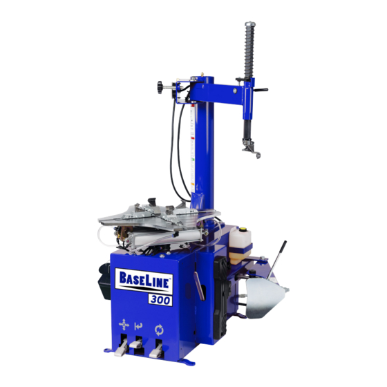
Rim Clamp
For servicing single piece automotive and
most light truck tire/wheel assemblies.
Model 300 Shown
See
RIM Safety
page 3
Operating
Instructions
on page 8.
Safety Instructions
Set Up Instructions
Operation Instructions
Maintenance Instructions
Tire Changers
®
Model 500 Shown
READ these instructions before
placing unit in service. KEEP these
and other materials delivered
with the unit in a binder near the
machine for ease of reference by
supervisors and operators.
Manual Part No.: 85610373 00
Revision:
01/16
Advertisement
Table of Contents

Related Manuals for Baseline 500

Summary of Contents for Baseline 500
- Page 1 Rim Clamp Tire Changers ® For servicing single piece automotive and most light truck tire/wheel assemblies. Model 300 Shown Model 500 Shown RIM Safety page 3 Operating Instructions on page 8. READ these instructions before Safety Instructions placing unit in service. KEEP these...
-
Page 2: Table Of Contents
Mount/Demount Tool Adjustment ........24 trademarks owned by Hennessy Industries, Inc. Robo-Assist Helper Arm Maintenance ......24 ® Baseline™ and Robo-Assist™ are trademarks owned Pressure Regulator Maintenance ........25 by Hennessy Industries, Inc. Oil Injector Maintenance ............25 Regal is a registered trademark owned by Chevron ®... -
Page 3: Tire Specifications Diagram
Tire Specifications Diagram Tire Specification Radial Rim diameter code Ratio of height to Load index & width (aspect ratio) speed symbol Nominal width of tire in millimeters U.S. DOT tire identification number Passenger car tire Severe snow conditions Max. Tire ply permissible composition inflation... -
Page 4: Safety Instructions
Definitions of Hazard Levels Safety Instructions Identify the hazard levels used in this manual with Owner’s Responsibility the following definitions and signal words: To maintain machine and user safety, the responsi- DANGER bility of the owner is to read and follow these instruc- Watch for this symbol: tions: •... -
Page 5: Safety Notices And Decals
Safety Notices and Decals Remember R.I.M. Three Simple Steps To Help Keep Shops Safe READ INSPECT MOUNT Failure to follow danger, warning, and cau- R.I.M. is a training program developed by Hennessy tion instructions may lead to serious per- Industries to help keep tire technicians safe. By fol- sonal injury or death to operator or bystander lowing the basic principles of R.I.M., technicians can or damage to property. -
Page 6: Set Up Instructions
Tower Installation Set Up Instructions CAUTION CAUTION STAY CLEAR OF MOVING PARTS when recon- Proper unit installation is necessary for safe necting the unit to the air supply. The position use and efficient operation. Proper instal- of control valves may have changed during lation also helps protect the unit from dam- the servicing of the machine. -
Page 7: Air Source
Air Source Remove swing arm bolt, washers and nut from The model 300 and model 500 require a 5 CFM air tower. Then, with the aid of a helper, position and source at 120 PSI. The operating pressure range is attach swing arm using bolt, washers and nut just between 110 PSI and 175 PSI at the machine. -
Page 8: Principal Operating Parts
Know Your Unit Principal Operating Parts Compare this illustration with the unit before placing it Do It Now! into service. Maximum performance and safety will be ✔ obtained only when all persons using the unit are fully Now is a good time to contact product service trained in its parts and operation. - Page 9 CAUTION Replace any damaged or missing safety decals. They are available from Hennessy Industries, Inc., (800) 688-6359. Pressure Safety Valve — The high pres- Clamp Control Pedal — Three-position sure safety valve is set to exhaust at line pedal that opens, holds or closes rim pressures above 185 PSI.
-
Page 10: Operation Instructions
Operation Instructions This unit must be properly operated and properly maintained to help avoid accidents that could dam- age the unit and injure the operator or bystanders. This section of the Operation Instructions manual reviews the basic operations and use of controls. These instructions should be reviewed with all employ- ees before they are allowed to work with the machine. - Page 11 Determine the mounting side of the wheel. The mounting side is the narrow side of the drop center. See figure 2 for more information on the drop center. Place tire/wheel assembly on table top with mounting side up (figure 9). Use the clamp control pedal to move the clamps inward (push pedal down) or outward (toggle pedal up).
- Page 12 The tool clearance may change with machine The mount/demount tool should be in contact with use and should be inspected often. Failure to the rim edge. Turn the swing arm adjusting knob to maintain the proper clearance may result in move the mount/demount tool away from the rim 1/8 damage to the wheel rim and/or tire.
- Page 13 Push the bead lifting tool down towards the wheel Lift and hold the tire at an angle so that the to lift the tire bead up and over the knob portion of the lower bead is resting in the drop center directly across mount/demount tool.
-
Page 14: Mounting
Mounting Before any mounting, inspect tire for damage and This information must be read and followed carefully verify size match between tire and wheel (figure 17). to prevent accidents and injuries during mounting. Attempts to force a bead seat on mismatched tires and wheels can cause the tire to violently explode, causing serious personal injury or death to operator and/or bystanders. - Page 15 If table top rotation stalls, reverse the table top Place tire over wheel and move swing arm into momentarily until tire bead is again loose on position making sure the valve stem is at the 9 o’clock the wheel. Reposition tire on Duckhead ®...
-
Page 16: Inflation
The inflation pedal, located at the rear of the left side Inflation of the machine, controls the flow of air through the inflation hose, and has three positions. Tire inflation is performed in three steps: BEAD SEAL, BEAD SEAT, and INFLATION. These steps are The clip-on chuck on the end of the hose explained in detail on page 18. -
Page 17: Bead Sealing
Bead Sealing CAUTION Remove the valve core from the valve stem to allow more air flow into the tire to assist with bead seal. Use of bead sealing jets without a tire in place Position valve stem in front of operator and con- can cause dirt and debris to be blown into the nect the inflation hose with the clip-on chuck. -
Page 18: Bead Seating
Bead Seating Once tire pressure is indicated on the air gauge (inflation pedal in position 1; foot removed from pedal), continue to inject air into the tire (inflation pedal position 2) in short intervals. Check the pressure frequently. Stand back during bead seat. Keep hands, NEVER exceed 40 PSI to seat beads while arms, and entire body away from tire during this pro- using this tire changer. -
Page 19: Inflation
Inflation NEVER exceed tire manufacturer’s recom- mended air pressure. Tires can explode, especially if inflated beyond these limits. Use clip-on air chuck, keep hands, arms and entire body back from inflating tire. Avoid distraction during inflation. Check tire pres- sure frequently to avoid over inflation. Exces- sive pressure can cause tires to explode, causing serious injury or death to operator or Figure 24 - Do Not Use a Hand-held Style Air Chuck... -
Page 20: Stages Of Inflation On A Conventional Tire And Rim
Stages of Inflation on a Conventional Tire and Rim Review these descriptions and diagrams carefully. Refer to them as necessary during bead sealing, bead seating, and inflation to verify that you are proceeding properly and safely. Bead Sealing Bead sealing is the process of capturing air pressure between the tire and the rim. -
Page 21: Mismatched Tires And Wheels
Mismatched Tires and Wheels Never attempt to mount and inflate mis-matched tires and wheels. Mismatched tire and wheel combinations can explode, causing personal injury or death to operator and/or bystanders. Important: Always read and follow operating instructions. • 19... -
Page 22: Operating Instructions (Using Robo-Assist™ Helper Arm)
Operating Instructions (using Locate the valve stem just before the mount/ demount tool before proceeding (Figure 27). Robo-Assist™ Helper Arm) Unit must be properly operated and properly main- tained to help avoid accidents that could damage the unit and injure the operator or bystanders. These instructions should be reviewed with all employees before they are allowed to work with the machine. -
Page 23: Mounting (Using Robo-Assist™ Helper Arm)
Mounting (using Robo-Assist™ Helper Arm) Lubricate both tire beads liberally. Performance tires will require more lubrication than standard pas- senger car tires. Mount the lower bead. In most cases, the lower bead will mount easily. Mounting the top bead can be very difficult when mounting new tires on performance and custom wheels. -
Page 24: Tube Type Tires
Tube Type Tires Mounting Avoid pinching or forcing the tube. Apply rubber lubricant to the tire beads of the tire. Mount the bottom tire bead. Round out the tube with a small amount of air. Apply rubber lubricant to the tube. Insert the tube into the tire. -
Page 25: Maintenance Instructions
Important: These instructions will help you service the Maintenance Instructions unit. Instructions are for a person with some mechani- cal ability and training. No attempt has been made to Read and follow all the maintenance instruc- describe all basic steps, for example, how to loosen tions provided in this manual to keep the or tighten fasteners. -
Page 26: Mount/Demount Tool Cleaning
Robo-Assist Maintenance Mount/Demount Tool Cleaning Robo-Assist Helper Arm Maintenance ® Clean dirt and debris from the Duckhead mount/ Grease the Robo-Assist Helper Arm to maintain ® ® demount tool roller with a small screwdriver or pick. smooth rotation. Grease fittings are installed at the pivot joints. -
Page 27: Pressure Regulator Maintenance
Pressure Regulator Maintenance Replace pressure regulator if it fails to shut air supply off at 60 PSI, or if it malfunctions in any other way. Do not operate machine with a faulty pressure regulator. Operating a tire changer with a defective, improperly adjusted, or by-passed pressure regulator could cause an operator to acci- dentally over pressurize a tire, resulting in a... - Page 28 AFETY R.I.M. READ INSPECT MOUNT READ… INSPECT… MOUNT… Mounting inflat- Before you put any tire Once you’ve made sure the tire is ing the wrong size tire on a rim, Inspect the rim OK and the right size and the rim is can get you hurt.
Need help?
Do you have a question about the 500 and is the answer not in the manual?
Questions and answers