DLS CA22 How To Install And Operate
Hide thumbs Also See for CA22:

Advertisement

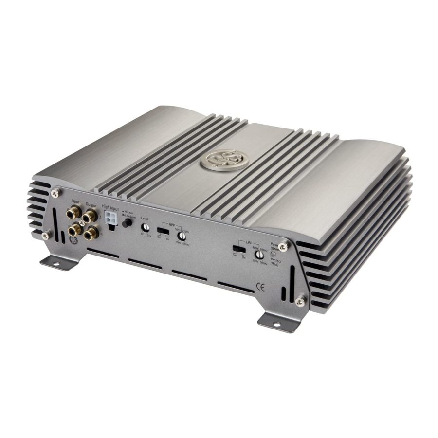
How to install and operate the DLS
CA22, CA23, CA31, CA41 and CA51
car audio amplifiers.
Welcome!
This owners manual is written in easy english and
uses a lot of drawings to simply the installation and
use of the above amplifiers.
Your DLS amplifiers must be installed correctly in
order to work well. This manual will show you how
to install the amplifier like a pro. Please read the
entire manual before beginning the installation.
Install the amplifier yourself if you feel confident with
our instructions and if you have the proper tools.
However if you feel unsure, turn over the installa-
tion job to someone better suited to it.
Warranty Service
This amplifier is covered by warranty, depending
on the conditions in the country where it is sold. If
the amplifier is returned for service, please include
the original dated receipt with the product.
Technical Assistance
For technical assistance ask the shop where the
product was sold or the distributor in your very coun-
try.
You can always phone the DLS Helpdesk in Sweden
+ 46 31 84 00 60 or send an e-mail to info@dls.se.
Information can also be found on our WEB-site
www.dls.se
Contents
Features...................................
Installation................................
Routing Wires............................
Power and Outputs.....................
Inputs and controls.....................
Input level control.........................
Grand Bass,Crossovers................
CA 22 and CA 23 speaker wiring:
Front speakers............................
Subwoofer.................................
Front speakers............................
Subwoofer.................................
Four speakers............................
active crossovers......................... 11
Four speakers............................
Subwoofer......................................
Testing......................................
Troubleshooting........................... 13
Professional tips..........................
Specifications.............................. 15
2
2
3
3
3
4
5
6
6
7
8
8
9
9
10
10
12
12
13
14

Advertisement

Table of Contents
loading

Summary of Contents for DLS CA22

  • Page 1: Table Of Contents

    You can always phone the DLS Helpdesk in Sweden + 46 31 84 00 60 or send an e-mail to info@dls.se. Information can also be found on our WEB-site www.dls.se...
  • Page 2: Features

    Important Allow air circulation around the amplifier. DLS logo on amplifier cooling flange The DLS logo on top of the amplifier is attached The DLS Classic series of amplifiers have a with two hex. screws. The logo can be removed...
  • Page 3: Tools And Materials Needed

    CA22, 23, 31, 41 & 51 Routing wires Tools and material needed Tools: Flat and Phillips screwdrivers Wire cutter Wire stripper Electric drill with drills Crimping tool Digital multimeter or test lamp Wire brush, scraper or a piece of an abrasive sheet to remove...
  • Page 4: Wiring

    CA22, 23, 31, 41 & 51 Wiring Power and Outputs Remote terminal ( REM ) Power terminal ( +12V) For RCA cable signal input: Connect the radio power antenna lead = remote Connect the fuse holder as close to the vehicle...
  • Page 5: Input And Controls

    Important High Input (A/B Ch) On CA22 & CA23 use either the low level or high White: A ch.+ level input, do not use both at same time. White/Black: A ch.- Grey/Black: B ch.- Grey: B ch.+...
  • Page 6: Input Level Control

    CA22, 23, 31, 41 & 51 Crossovers Hi / Low level input switch All DLS Classic amplifiers include high pass filter To ensure best possible performance from the amplifiers a switch is installed to select between Hi ( HPF ) and low pass filters ( LPF). On CA23 the and Low input.
  • Page 7: Ca 31, Ca 41, Ca 51 Crossovers

    E has also a subsonic filter that can be switched IN- OUT. The subsonic filter has a fixed frequency of Channel A/B is equipped very much like the CA22 25 Hz. The CA51 has also a phase control variable and CA23, however the LPF has a multiplier. Thus from 0 - 180 degrees.
  • Page 8 CA22, 23 Speaker wiring CA 22 & CA23 One subwoofer connected in bridge mode to Two fullrange speakers to CA22 or CA23 CA22 or CA23 NOTE! Filter settings 4 ohm minimum load when using bridge mode Subsoni c connection. Lower impedances may damage the...
  • Page 9: Front Speakers

    CA31 Speaker wiring CA 31 Two fullrange One (or two) speakers to 4 ohm + C CH - channel A/B subwoofers to channel C With the HPF-filter in OFF position the amplifier allows 90Hz 120Hz the speakers to play fullrange. If you for some Off On 50Hz 150Hz reason want to limit the low...
  • Page 10: Front Speakers

    CA41 Speaker wiring CA 41 Four fullrange speakers to CA41. One pair in Two fullrange speakers and one subwoofer to front and one pair in rear. CA41. Rear speakers Front speakers Rear subwoofer Rear or front speakers Filter settings A/B Channels Filter settings A/B Channels Multiply Multiply...
  • Page 11: Two Way Front System With Active Crossovers

    CA41 Speaker wiring CA 41 One 2-way speaker system to CA41 using active crossover between tweeter and midrange Midrange Tweeters Filter settings A/B Channels Multiply 50Hz 220Hz 80/800Hz 200/2(k)Hz x1 x10 Off On 15Hz 500Hz 50/500Hz 500/5(k)Hz Off On We want a crossover point of 4 kHz between tweeter and midrange.
  • Page 12: Subwoofer

    CA51 Speaker wiring CA 51 Four fullrange speakers to CA51. One pair in Subwoofer to CA51 front and one pair in rear. The CA51 is a five channel amplifier. On channels A/B, C/D the filter configuration is exactly the same as for CA41.
  • Page 13: Testing

    4. Check the amplifier protection fuses. Are these broken change to new ones with the same value. If short circuiting continues, contact your local DLS dealer. A fault may exist in the amplifier. 5. To start the amplifier requires a remote voltage of Test power wiring 9-15 volt.
  • Page 14: Professional Tips

    CA22, 23, 31, 41 & 51 Professional Tip: Professional Tip: NOISE PROBLEMS SPEAKER POLARITY CHECK. WHINING NOISE VARYING WITH ENGINE All speakers in a car audio system should be REVOLUTIONS: connected in phase (the same polarity). All spea- ker cones must move in the same direction. Out of...
  • Page 15: Specifications

    CA22, 23, 31, 41 & 51 Specifications DLS CLASSIC CA 22 CA 23 CA41 Number of channels RMS power out, 4 ohm (0,1% THD) 2 x 60 W 2 x 135 W 4 x 70 W All above output power...
  • Page 16 DLS Svenska AB P.O. Box 13029 SE-40251 Göteborg, Sweden Tel: +46 31 840060 Fax: +46 31 844021 E-mail: info@dls.se www.dls.se...

This manual is also suitable for:

Ca23Ca51Ca31Ca41Classic06Performance series

Table of Contents