
Related Manuals for Studiomaster digiLiVE 8C


Summary of Contents for Studiomaster digiLiVE 8C
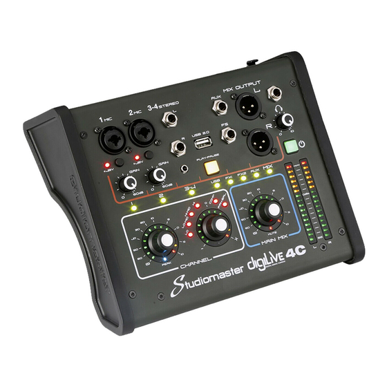
- Page 1 PICTURES OF 4C and 8C digiLiVE 4C and 8C Digital Mixing Consoles USER GUIDE Issue 0.65...
-
Page 2: Table Of Contents
Contents INTRODUCTION ........................4 THE USER GUIDE......................4 SAFETY INSTRUCTIONS ....................4 Unpacking Your digiLiVE ..................... 5 Powering Your digiLiVE ....................5 FRONT PANEL ........................6 INPUTS ........................... 7 Mic ................Error! Bookmark not defined. Stereo Input ......................8 USB 2.0 (Music) Input ....................8 Main Mix Outputs ..................... - Page 3 FOOT SWITCH SUB-PAGE ................... 41 DIRECT FUNCTION BUTTONS ................... 42 ① COPY ........................ 42 ② PASTE ....................... 42 ③ MUTE GROUP ....................42 CONNECTION EXAMPLES ..................43 digiLiVe 4C ......................43 digiLiVe 8C ......................43 digiLiVE 4C/8C SPECIFICATIONS ..................45...
-
Page 4: Introduction
This User Guide is designed to help you to get going with your digiLiVE 4C or 8C as quickly as possible. It will take you on a tour through the operational features of these two mixers explaining in detail the function of each input, output, knob and switch. -
Page 5: Unpacking Your Digilive
Unpacking Your digiLiVE When you unpack your digiLiVE console you will find the following: 1. digiLiVE console 2. Console Power Supply Unit (PSU) 3. IEC power cable 4. Wi-Fi network access point dongle (normally plugged into the rear panel USB 2.0 connector) Powering Your digiLiVE Your digiLiVE is powered from the 12 V DC power supply (PSU) packed separately in the... -
Page 6: Front Panel
FRONT PANEL The digiLiVE 4C features two mono Mic/Line input channels (each with combination XLR/TRS jack connectors and switchable phantom power); stereo Left and Right line-level inputs (TRS jack or stereo minijack); and one stereo USB Input for music playback (mp3 or WAV files). -
Page 7: Inputs
A Red LED on each channel indicates that phantom power is active on that channel. On the digiLiVE 4C the phantom power is switched via hidden switch that can be accessed with a paperclip or similar tool. -
Page 8: Stereo Input
OUTPUTS AUX Outputs These two outputs (one only in digiLiVE 4C) allow you to send mixes to active loudspeakers or to power amplifier and loudspeaker combinations in order to provide on-stage monitoring and/or an additional FOH feed. The mix to these outputs cannot be controlled from the digiLiVE front panel. -
Page 9: Front Panel Controls
FRONT PANEL CONTROLS The digiLiVE 4C and 8C hardware controls are minimalist, simple and intuitive, and allow you to access the essential gain, 4-band EQ, level, compressor, pan/balance and stereo mix input and output console functions directly, and virtually instantly, from the front panel. -
Page 10: Digilive Html Control Application
digiLiVE HTML CONTROL APPLICATION HTML App Access – Wi-Fi Since it is hosted on the digiLiVE itself, accessing the HTML Control application is simply a matter of logging onto the digiLiVe’s 2G wireless network. 1. Ensure that the Wi-Fi dongle supplied with your digiLiVE console is plugged into one of the two USB 2.0 connectors (the rear panel one is recommended). -
Page 11: Channels Screen
CHANNELS SCREEN FULL MODE Above is a computer screenshot showing the digiLiVE 8C Channels screen when the control app is running in Full mode, in which all the available faders and sub-page tabs are displayed. Depending on the screen size you are using, you may see fewer faders. Swiping left or right, or using the Left-Right Arrow buttons will allow you to access any hidden faders. -
Page 12: Basic Mode
BASIC MODE In Basic mode, access to the Monitor tab in the left-hand menu and to the Preamp and Dynamics tabs in the channel menu bar is removed. In addition, the EQ tab and the Compressor function from the Dynamics tab are combined into a single EQ/Comp tab. LOCK MODE In Lock mode, access to the left-hand menu and to the channel menu bar is removed entirely. -
Page 13: Input Channels
INPUT CHANNELS The MIC (microphone/line input) input channel contains four individual modules: Preamp, EQ, Dynamics and Bus Send (which incorporates Aux and Effects send). Touching a module tab will bring up a sub-page with further options. ① Preamp Shows the status of Phase Reverse and Input Delay Time ②... -
Page 14: Mic Eq Sub-Page
MIC EQ SUB-PAGE (Touch Tab to Open) The EQ module is a 4-band fully-parametric EQ that can be set up on screen via touch. ① Change Input Press the arrow-buttons to select the previous or next input. ② Flat Single-touch to set all EQ bands flat. This cannot be undone. The HPF ⑤ is not affected. ③... - Page 15 Gain: each band can be adjusted between -18dB and +18dB. Default setting is 0dB. Q: allows bandwidth adjustment from 0.5(wide) to 10.0(narrow). Default is 0.5. Library The library function allows you to save and load up to 16 User EQ presets. Tap the dropdown button, select a preset from the list and tap OK to load its EQ settings.
-
Page 16: Mic Dynamics Sub-Page
MIC DYNAMICS SUB-PAGE (Touch Tab to Open) The Dynamics consist of a gate and a separate compressor ① Change Input Press the arrow-buttons to select the previous or next input. ② Gate Single press IN to enable the Gate (button turns green), press again to disable it (button goes dark). - Page 17 ④ Compressor Single press Bypass to disable the Compressor (button turns yellow). Press again to enable the Compressor (button goes dark). Default is Bypass. The Compressor Curve indicates the gain relationship between input signals and output signals. The curve is split into two parts – below and above the Threshold value. Any signal below the threshold will pass the compressor virtually unmodified, while signals above the threshold will be attenuated (i.e.
-
Page 18: Mic Bus Send Sub-Page
MIC BUS SEND SUB-PAGE (Touch Tab to Open) Each input channel can send signals to 2 Mono busses (AUX 1 & AUX 2), 4 FX busses (REVerb 1&2, DELay 1&2) and Main Mix L-R. ① Change Input Press the arrow-buttons to select the previous or next input. ②... -
Page 19: Stereo Input
STEREO INPUT (7-8) The Stereo Input 7-8 input channel contains four individual modules: Preamp, EQ, Dynamics and Bus Send (which incorporates Aux and Effects send). Touching a module tab will bring up a sub-page with further options. ① Preamp Shows the status of Phase Reverse and Input Delay Time. ②... -
Page 20: Stereo Input Eq, Dynamics And Bus Send Modules
③ Sum Sums left and right input, so both sides of the stereo channel will contain the same (mono) signal. This can also be used to route the signal to both channels in case there is only one jack plugged into the stereo input. Touch the button to enable (button turns green, label changes to “On”), and touch again to disable (button goes dark, label changes to “Off). -
Page 21: Music (Usb 2.0 ) Input
MUSIC (USB 2.0 ) INPUT The Music (USB 2.0) Input allows you not only to connect a USB Drive containing mp3 and WAV format audio files and to replay these files through your digiLiVE console, but also to record the Main Mix output (including the audio from any mp3/WAV file playing at the time) to a stereo WAV file. -
Page 22: Music (Usb 2.0) Input Preamp Sub-Page
MUSIC (USB 2.0) INPUT PREAMP SUB-PAGE (Touch Tab to Open) ① Change Input Touch the arrow-buttons to select the previous or next input. ② Phase Reverse Touch to invert phase (button turns green, label changes to “On”). Touch again for normal phase (button goes dark, label changes to “Off”). -
Page 23: Music Player
MUSIC PLAYER Touching the Music tab opens the Music Player and calls up the Music (USB 2.0) input. ① Track Listing Shows the names and file types of all mp3 and WAV files in the root directory of a USB drive inserted into the Music USB 2.0 channel connector. -
Page 24: Fx (Effects)
The digiLiVE 8C’s FX (Effects) are made up of four processing modules – two reverbs (REV1 and REV2), and two delays (DEL1 and DEL2). The digiLiVE 4C has only two modules – REV1 and DEL1. Using the Input Channel Bus Send Sub-Page, you can route sends from any input channel to any or all of the four FX. - Page 25 Reverb Times Default Hall 0.8 s 12.0 s 1.6 s Room 0.4 s 8.0 s 0.8 s Plate 0.4 s 6.0 s 0.6 s ③ Reverb Time Trim This fader allows you to trim the available reverb time of the selected reverb type. The numerical display next to the fader shows the current trim (0%-100%) of the full reverb time.
-
Page 26: Delay Sub-Page
DELAY SUB-PAGE Touch the “DEL1 or DEL2” button in the FX Sub-page to access the Delay Sub-Page. ① FX Tabs Touching a tab opens the sub-page for the selected delay. ② Delay Type Touching the down-arrow opens a sub-menu showing the available reverbs types. Touch a Delay Type to select it and touch “OK”... - Page 27 Delay Time can be configured as a multiple of BPM by using Factor and Tempo. Factor corresponds to coarse tuning, whilst Tempo corresponds to fine tuning. For example, if you set the Factor to 8 and the Tempo to 120 BPM, the resulting Delay Time is 500ms 60*1000/120=500).
-
Page 28: Outputs
① FX OUTPUTS The REV1, REV2 and DEL1, DEL2 outputs can be routed, via their respective sub-pages, to AUX1, AUX2 and the L-R Mix. The digiLive 4C has only two FX modules, REV1 and DEL1. ② AUX OUTPUTS The AUX1 and AUX2 outputs can, if required, also be routed to the L-R MIX via their respective Bus Send tabs. -
Page 29: Geq Page
GEQ PAGE Touch the GEQ button above the L-R Mix fader to activate the GEQ (Graphic Equaliser). The GEQ button turns yellow and GEQ Page opens. Touch the button again to deactivate the GEQ. The GEQ button turns black, the GEQ page closes and the Channels page opens. The faders are arranged in four banks. -
Page 30: Meters Page
METERS PAGE This page can be accessed by a single touch on the Meters tab in the left-hand menu. This page is arranged in two parts, with Input Channel signal levels shown at the top and Output Channel signal levels at the bottom. Input channel s ignal levels can be displayed either Pre-Fader or Post-Fader. -
Page 31: Monitor Page
MONITOR PAGE On the upper right of the digiLiVE 4C and 8C front panel you will find a Headphone jack connector, together with an analogue rotary potentiometer to control the headphone volume. The headphone input comes from the stereo Monitor Bus, whose operation is configured on the Monitor Page. -
Page 32: Oscillator
② PFL Trim and Mute In PFL mode, PFL Trim attenuates the incoming signal from a channel to compensate for the level difference between PFL and AFL signals. The attenuation ranges for 0dB to -76dB. Default is 0dB. Adjust the Level value by touching and dragging the virtual PFL Trim rotary encoder on the touch screen. -
Page 33: Scenes Page
SCENES PAGE The Scenes Page allows you to store complete “snapshots” of all digiLiVE channel Preamp, EQ, Dynamics, Bus Send, FX, Meter, Monitor and Settings parameters as “Scenes”. To open the Scenes page, touch the Scenes tab on the left-hand menu. ①... - Page 34 Copy:Touch the Scene name to select it, and then touch the Copy button. A “Please enter a new name” dialogue pop-up appears. You will see that the digiLiVE has automatically generated a new name (“Scene Name”_Copy_0). You can accept this name by touching “OK”, edit the new name and touch ”OK”...
-
Page 35: Settings Page
SETTINGS PAGE This page allows you to access System Information, Wi-Fi/LAN Network configuration, the Error Message Log, and Mute Group and Foot Switch configuration. To open this page, touch the SETTINGS tab in the left-hand menu. ① General Sub-Page This page displays System Version, Serial Number, LAN and Wi-Fi MAC addresses and the time and date of the firmware build. -
Page 36: Network Sub-Page
NETWORK SUB-PAGE This page is where you configure the digiLiVE Wi-Fi Hotspot and LAN settings. This page is accessed by touching the NETWORK tab in the SETTINGS page. ① Touch the Setup button to enter Network Setup. A sign-in screen opens. ②... - Page 37 Although last on the list, the Network Status page opens first as this will be the Network page that you probably will use most often in checking the status of network connectivity. ③ This is where you will see the active network status. Touch the words “Wi-Fi Setup”...
- Page 38 DHCP (Dynamic Host Configuration Protocol). Please contact the local Network Administrator for network connection details. Studiomaster recommends that you physically connect the digiLiVE to the new LAN network before making changes to the LAN Configuration.
-
Page 39: Log Sub-Page
LOG SUB-PAGE Touch the Log tab on the Settings Page to open the Log Sub-Page. ① This page displays the list of System Log messages generated automatically by the digiLiVE whenever a system message is generated. In the unlikely event of you experiencing issues with your digiLiVE, you may be asked to send these messages to our service department. -
Page 40: Mute Group Sub-Page
MUTE GROUP SUB-PAGE Touch the “Mute Group” tab on the Settings Page to open the Mute Group page. This page is where you add and remove Input, Output and FX Channels to and from the digiLiVE’s single Mute Group. ① Clear Touching the Clear button clears all assignments (all buttons turn Dark). -
Page 41: Foot Switch Sub-Page
FOOT SWITCH SUB-PAGE Touch the Foot Switch tab on the Settings Page to open the Foot Switch Sub-Page. This page allows you to freely assign the Reverb and Delay Effects to either of the digiLiVE’s two footswitches for muting. ① Foot Switch Select Touch Foot Switch 1 or Foot Switch 2 Select button to select a Foot Switch for Effects assigned to (button has a highlit border). -
Page 42: Direct Function Buttons
DIRECT FUNCTION BUTTONS The digiLiVE features three Direct Function buttons. These sit in a group at the bottom of the left hand menu. ① COPY The digiLive Copy function allows you to copy the settings of the Preamp, EQ, Dynamics and Bus Send modules of one Input Channel - either in their entirety or individually - from one Input Channel to another. -
Page 43: Connection Examples
CONNECTION EXAMPLES digiLiVe 4C digiLiVe 8C... -
Page 44: Service Information
SERVICE INFORMATION If you have a problem with your Studiomaster product or think it has developed a fault, contact your local dealer or distributor for service details. Should it be recommended that you return the product to your nearest Studiomaster Service Centre you must first contact them. -
Page 45: Digilive 4C/8C Specifications
4C/8C SPECIFICATIONS Input Characteristics Output impedance of signal generator:150Ω Input Input Impedance Connector Maximum Input Sensitivity Range MIC INPUT 1.5KΩ +16 dBu 60dB (Balanced) +60dBu LINE INPUT 10KΩ TRS(Balanced) +30 dBu +40dBu ST INPUT 10KΩ TRS(Balanced) +22dBu 40dB +20dBu... -
Page 46: Specifications
Input Function Output Function Function Parameter Function Parameter Phase Normal/Reverse Delay 0 msec to 200 msec Delay 0 msec to 200 msec Insert 1GEQ FX (Effects) 2Reverb / 2Delay L-R Pan CSR= 0% to 100% Fader Level:–80dB to +10 dB Threshold= –80dB to 0dB LISTEN On/Off... - Page 47 STUDIOMASTER Unit 11, Torc:MK, Chippenham Drive, Milton Keynes MK10 0BZ, United Kingdom Tel: +44 (0)1908 281072 Email: enquiries@studiomaster.com Web: www.studiomaster.com...
Need help?
Do you have a question about the digiLiVE 8C and is the answer not in the manual?
Questions and answers