Table of Contents

Related Manuals for Aquion Energy S30-0080


Summarization of Contents
Introduction
1.1 About This Manual
Provides technical information and safe practices for receiving, installing, and operating Aquion Energy battery products.
1.2 Contact Information
Details Aquion Energy's mailing address, telephone number, and website for inquiries and support.
Product Information
2.1 Product Overview
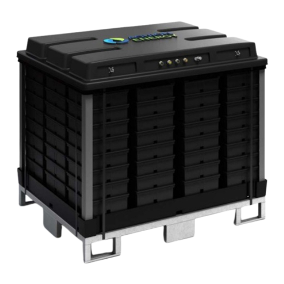
Describes Aquion's Aqueous Hybrid Ion (AHI™) batteries, their applications, and the S-Line/M-Line product families.
2.2 Product Specification
Directs users to product specification sheets for details on voltage curves, efficiency, and current ratings.
2.3 UL Recognition
Lists the UL certification tests completed for the S-Line Battery Stack, covering various safety and performance standards.
2.4 Cradle to Cradle Certification
States that the S30-0080 Battery Stack is Cradle to Cradle Certified™ Bronze, highlighting product sustainability aspects.
2.5 M110-LS83 Electromagnetic Compatibility
Discusses FCC and CE compliance, including potential interference issues and operational conditions.
Safety Information
3.1 Electrical Hazards
Warns about live terminals and general electrical hazards present in battery systems and associated electronics.
3.2 Electrical Safety
Details electrical safety requirements for S-Line stacks (current limits) and M-Line modules (fuses).
3.3 Chemical Hazards
States AHI battery materials are non-toxic, detailing electrolyte contact procedures and leak behavior.
3.4 Gas Emissions
Addresses potential trace gas emissions (H2, O2, CO2, CO) during normal operation and overcharging.
3.5 Weight Hazards
Specifies the weight of S-Line stacks (118 kg) and M-Line modules (1,504 kg) and handling precautions.
3.6 Ingress Protection
Presents the IP Code classifications for battery stacks (IP22) and modules (IP2X) regarding solid and liquid ingress.
3.7 Decommissioning Hazards
Provides guidance on safe disposal of AHI batteries, emphasizing compliance with regulations and avoiding environmental contamination.
Transportation and Receipt of Product
4.1 Shipping
Covers shipping configurations, ISTA testing, and requirements for shipping batteries at a low state of charge.
4.2 Disassembly Hazards
Warns against disassembling battery stacks due to compression, which can cause performance issues or injury.
4.3 Packaging
Details how S-Line stacks and M-Line modules are packaged, including the use of Tip-N-Tell indicators.
4.4 Delivery Inspection
Instructs users to inspect for damage upon delivery, noting indicators like torn packaging or tripped indicators.
Installation
5.1 Unpacking
Provides instructions for unpacking battery stacks and modules, and checking for missing or damaged items.
5.2 Site Requirements
Outlines requirements for installation sites, including exposure, enclosure, size, weight, and ventilation.
5.3 Moving
Details procedures for moving S-Line stacks and M-Line modules, including lifting and tilt restrictions.
5.4 Placement
Provides placement guidelines, including connecting module fuses and setting up the BMS before restricting access.
5.5 Battery Module Fuse Connection
Explains how to connect the 12 pre-installed but disconnected 20-A fuses in the M-Line battery module.
Electrical Integration
6.1 Electrical Interfaces and Connections
Details electrical connectors and accessories for S-Line stacks and M-Line modules.
6.1.1 Stack Connectors
Identifies the negative (Female Amphenol Helios H4) and positive (Male Amphenol Helios H4) connectors on the S-Line Battery Stack.
6.1.2 Stack Accessories
Lists required and recommended connectors and tools for S-Line stack connections, sourced from Amphenol distributors.
6.1.3 Module Connectors
Details the negative (-) and positive (+) battery terminals for the M-Line Battery Module, including connector part numbers.
6.1.4 Module Accessories
Lists power and communication cables (4-pin miniBOSS, DeviceNet) required for M-Line module connections.
6.1.5 Module Contactor Control
Explains the DC contactor on each module, powered by 24V, and its integration with BMS and ESTOP systems.
6.2 Product Wiring Diagrams
Presents wiring diagrams for the S-Line Battery Stack and M-Line Battery Modules.
6.5 Parallel Wiring
6.5.1 Monitoring
Explains the Aquion BMS-200 connectivity to sensing boards or SMI-100 interfaces for monitoring up to 16 modules/stacks.
6.5.2 Overcurrent Protection
Details overcurrent protection requirements based on local codes to prevent exceeding rated current limits.
6.5.3 Grounding
Provides instructions for grounding S-Line Battery Stacks using the tie rod and M-Line modules via the grounding lug.
Commissioning
7.1 Initial Charge
Instructs on initial charging of batteries shipped at low SOC, emphasizing use of battery-specific charging devices.
7.2 Voltage Matching
Requires matching S-Line stack voltages within 5 Vdc before parallel connection to prevent damage and ensure safety.
7.3 Configuring Inverters and Charge Controllers
Guides users on configuring inverters/charge controllers for 48 V systems, referencing manual sections and operational settings.
Operation
8.1 Operational Limits
Defines operational limits including current, voltage, and ambient temperature for optimal performance and longevity.
8.1.1 Current
Specifies maximum charge/discharge current limits for S-Line stacks (17 A) and M-Line modules (204 A).
8.1.2 Voltage
States the required operating voltage range for battery stacks and modules after initial charge (40-57.6 Vdc).
8.1.3 Ambient Temperature
Defines the 24-hour average ambient temperature range (-5°C to 40°C) for battery operation.
8.1.4 Configuration
Recommends monitoring for parallel systems and notes capacity limits for stacks (192) and modules (16) with BMS.
8.2 Charge Profiles
Introduces charge profile terminology (bulk, absorption, float) for AHI chemistry and directs to online settings.
8.2.1 Recommended Charge Profile
Details the recommended charge profile for obtaining optimal energy and capacity, including current and voltage parameters.
8.2.2 Boost Charge Profile
Describes the boost charge profile for UPS/backup applications that discharge infrequently, with specific conditions.
8.2.3 Three-Stage Charge Profile
Explains the three-stage charge profile for systems that require float settings or do not use current termination.
8.3 State of Charge
Discusses maintaining partial state of charge and methods for determining the battery's state of charge.
8.3.1 Partial State of Charge
States that AHI batteries tolerate partial SOC and do not require equalization charges for battery life.
8.3.2 Determining State of Charge
Explains how to estimate state of charge by measuring the open circuit voltage (OCV) after a resting period.
8.4 Discharging
Specifies the maximum discharge current for S-Line stacks (17 A) and M-Line modules (204 A).
8.5 Self-Discharge
Details capacity loss due to self-discharge, which is temperature-dependent and recoverable by recharging.
8.6 Long-Term Storage
Provides guidelines for long-term storage, including removing connections and environmental conditions (-10°C to 40°C).
8.7 Recycling and Disposal
Instructs on proper recycling and disposal of AHI batteries according to federal, state, and local regulations.
8.8 Record Keeping
Recommends maintaining system documentation, including single-line diagrams and settings logs.
Need help?
Do you have a question about the S30-0080 and is the answer not in the manual?
Questions and answers