
Related Manuals for ARCA GRA50RO


Summary of Contents for ARCA GRA50RO
- Page 1 www.arcacaldaie.com...
- Page 3 ARCA s.r.l. declines all liability for any imprecisions due to transcription or printing errors. It likewise reserves the right to make any changes to its products that it considers necessary or useful, without these affecting the essential features of such products. This documents is also available as a PDF file.
-
Page 4: Table Of Contents
GENERAL WARNINGS ..........................6 TECHNICAL SPECIFICATIONS AND DIMENSIONS .................7 2.1. TECHNICAL SPECIFICATIONS AND DIMENSIONS OF MODELS GRA14RO,GRA20RO, GRA30RO ....7 2.2. TECHNICAL SPECIFICATIONS AND DIMENSIONS OF MODELS GRA40RO, GRA50RO ........8 2.3. TECHNICAL SPECIFICATIONS AND DIMENSIONS OF MODELS GRA80RO ............. 9 2.4. - Page 5 8.2.3. EXAMPLE DIAGRAM FOR HEATING WITH CLOSED VESSEL, PLATE HEAT EXCHANGER, TWO-COIL DHW STORAGE CYLINDER AND SOLAR PANELS .........................38 8.3. EXAMPLE DIAGRAMS FOR HEATING SYSTEM WITH BUFFER TANK OR COMBI BUFFER TANK ....39 8.3.1. EXAMPLE DIAGRAM FOR HEATING WITH COMBI BUFFER TANK AND SOLAR PANELS..........40 8.3.2.
-
Page 6: General Warnings
GENERAL WARNINGS This instruction booklet is an integral and essential part of the product and must be provided to the user. Carefully read the warnings contained in this booklet, as these provide important safety instructions for the installation, use and maintenance of the product. This booklet should be carefully kept for future reference. The appliance must be installed by professionally qualified personnel or by our service centre in compliance with local legislation in force and the instructions provided by the manufacturer. -
Page 7: Technical Specifications And Dimensions
TECHNICAL SPECIFICATIONS AND DIMENSIONS 2.1. Technical specifications and dimensions of models GRA14RO, GRA20RO and GRA30RO Key: Fuel container (granular fuel storage) Central heating flow outlet Fuel inlet Central heating return inlet Flame inspection opening Boiler drain Top door (furnace) Safety heat exchanger attachments Burner cover plate Boiler probe socket attachment (S4) Bottom door (ash dump) -
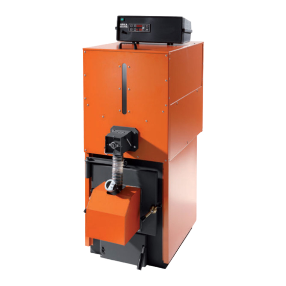
Page 8: Technical Specifications And Dimensions Of Models Gra40Ro, Gra50Ro
2.2. Technical specifications and dimensions of models GRA40RO and GRA50RO Key: Fuel container (granular fuel storage) Central heating flow outlet Fuel inlet Central heating return inlet Flame inspection opening Boiler drain Top door (furnace) Safety heat exchanger attachments Burner cover plate Boiler probe socket attachment (S4) Bottom door (ash dump) Chimney attachment... -
Page 9: Technical Specifications And Dimensions Of Models Gra80Ro
2.3. Technical specifications and dimensions of models GRA80RO Key: Fuel inlet Central heating return inlet Flame inspection opening Boiler drain Top door (furnace) Safety heat exchanger attachments Burner cover plate Boiler probe socket attachment (S4) Bottom door (ash dump) Chimney attachment Cleanout door Thermal relief valve socket attachment Fan motor (flue gas exhaust) -
Page 10: Main Parts Of The Boiler
Minimu Maximu Minimum Maximum Weight Boiler Water side Flue gas Operating Max test m heat m heat heat heat capacity pressure side pressure pressure output output input input drop pressure Model drop kcal/h kcal/h kcal/h kcal/h litres mbar. mbar. bar. bar. -
Page 11: Screw (Code Coc0502) For Models Gra80Ro, Gra115Ro, Gra150Ro
3.2. Screw (CODE COC0502) for models GRA80RO, GRA115RO, GRA150RO In versions 80, 115 and 150 the screw is supplied separately. Versions 30, 40, 50 can be supplied with the fuel container and screw separately on request. 1920 1694 Key: 1. Screw gear motor When starting the boiler for the first time the 2. -
Page 12: Pellet Burner
3.4. Pellet burner WARNING: The cover on inspection opening 7 must be kept closed during ignition and shut-down. Key: Photocell Power outlet for boiler panel connection Secondary air adjustment Door for primary air adjustment Ignition heater Flame inspection opening cover Stainless steel perforated grid plate Pellet inlet 3.5. -
Page 13: Smokebox And Fan
To minimise the possibility of condensate forming in the wood-fired boiler, a recirculating pump needs to be installed. The pump is connected between the outlet (A1) and return (A2) fittings, with the direction of flow from top down. ARCA supplies a recirculating pump kit as an accessory, including pump, connection piping and fittings. -
Page 14: Installation
INSTALLATION The Granola AUTOMATIC boiler is no different from a normal solid fuel boiler; therefore, there are no specific installation instructions beyond the safety requirements of the relevant standards in force. The room must be well ventilated; ventilation openings must have a minimum total surface area no less than 0.5 m . -
Page 15: Sy400 Electronic Panel (Code Pel0100Duo)
SY400 ELECTRONIC PANEL (CODE PEL0100DUO) Key: 1. Main switch 2. Safety thermostat 3. Display keypad 5.1. Display The figure below shows the control unit operator panel, with the key to the functions of each component:... -
Page 16: Electronic Board
5.2. Electronic board (inside the panel) -
Page 17: Probe Connections
5.3. Probe connections For correct boiler operation the water temperature probes and safety thermostat sensor must be positioned correctly. The control unit comes pre-wired with the outlet probe S4 - 3 m of cable (terminals 47, 48 page 15), the return probe S5 - 3 m of cable (terminals 45, 46 page 15) and the safety thermostat (terminals 63, 64 page15). -
Page 18: Terminal Block Wiring Connections
5.5. Terminal block wiring connections KEY: Central heating system pump Recirculating pump (anti-condensation) DHW storage cylinder or buffer tank/combi buffer tank pump Solar panel pump Room thermostat Door micro switch Selector valve NOTE: Contacts 16 and 17 (TA) are jumpered to allow continuous operation of the system pump if the room thermostat is not connected. -
Page 19: Commissioning And Operation
COMMISSIONING AND OPERATION Before starting the boiler, check that: a) the system is full of water and vented b) any on-off devices are open and that the pumps are not blocked; moreover: − Before performing any maintenance always disconnect power to the boiler and wait for the appliance to reach room temperature. -
Page 20: Flame Stabilisation
Ignition time may vary due to the different types of pellets available on the market (the maximum duration allowed for each attempt is set at 10 minutes). 6.3. Flame stabilisation Once the flame has ignited the flame stabilisation stage begins (fixed duration 3 minutes) and the top display shows “STB”. -
Page 21: Total Shutdown
6.8. Total shutdown The boiler can be shut down at any time by pressing button 7 for 5 seconds. In this way, the boiler remains off even when the outlet temperature decreases. The total shutdown stage also waits for the flue gas temperature fall below... -
Page 22: Water Circuit Configuration Menu
CLOCK BOILER PROGRAMMING BY TIMER THERMOSTAT MANUAL SCREW LOADING WITH EMPTY TANK TEST 220 V OUTPUTS 7.1. Water circuit configuration menu (enable probes) Depending on the type of water circuit connected to the boiler, the temperature probes need to be enabled for managing the pump electrical signals. -
Page 23: Display Menu (Display Probe Readings)
The following table indicates the values for enabling the probes based on the type of water circuit used: System configuration Description Water probes used Pumps used [P37] Boiler outlet probe S4 System pump (PI) Heating only Boiler return probe S5 Anti-condensation pump (PR) Boiler outlet probe S4 System pump (PI) - Page 24 The following table shows all the possible codes depending on which probes have been enabled: ITEM DISPLAY DESCRIPTION FLAME BRIGHTNESS (always displayed) FLUE GAS TEMPERATURE IN °C (always displayed) OUTLET WATER TEMPERATURE IN °C (always displayed) RETURN WATER TEMPERATURE IN °C (always displayed) CYLINDER / BUFFER TANK TOP TEMPERATURE IN °C...
-
Page 25: Clock Menu
SOLAR PANEL TEMPERATURE IN °C (only displayed if enabled) WATER TEMPERATURE DIFFERENTIAL BETWEEN OUTLET AND RETURN IN °C (always displayed) TEMPERATURE DIFFERENTIAL BETWEEN SOLAR PANELS AND CYLINDER / BUFFER TANK BOTTOM IN °C (only displayed if enabled) BOARD PROGRAM VERSION (always displayed) 7.3. -
Page 26: Timer Programming Menu
7) Press MENU (the minutes value starts flashing). 8) Use buttons 3 and 4 to set the minutes. 9) Press MENU (the day value starts flashing). 10) Use buttons 3 and 4 to set the day. 11) Press MENU. 12) Press ESC to exit or wait 40 seconds to automatically exit the menu. 7.4. - Page 27 8) Use buttons 3 and 4 to set the type of program. 9) Press MENU to confirm. SETTING THE DAILY PROGRAM: The DAILY program is used to set the boiler on / off times for the individual days of the week. For each day of the week there are 3 time bands available (each has an ON time and an OFF time).
- Page 28 14) Repeat the same operations described above to set the OFF time. 15) Press button 3 to set the second program or select the time band for the second day, third day, etc. SETTING THE WEEKLY PROGRAM: The WEEKLY program is used to set the same boiler on / off times for every day of the week. Three time bands are available (each has an ON time and an OFF time).
- Page 29 9) Press MENU. 10) Set the hours using buttons 3 and 4. 11) Confirm by pressing the MENU button. 12) Set the minutes using buttons 3 and 4. 13) Confirm by pressing the MENU button. 14) Repeat the same operations described above to set the OFF time.
- Page 30 8) Enable the time band and clear the dashes by holding button 7 for 5 seconds. Set the ON time, which will be the same for all days from Monday to Friday. 9) Press MENU. 10) Set the hours using buttons 3 and 4. 11) Confirm by pressing the MENU button.
-
Page 31: Manual Screw Loading Menu
7.5. Manual screw loading menu In OFF mode this is used to manually load the screw by completely filling the pipe that houses the screw. PROCEED AS FOLLOWS: 1) Press MENU. 2) Press button 3 repeatedly until the top display shows LOAD. 3) Press MENU. - Page 32 10) The top display shows the parameter being tested, FUM2. * Parameter FUM2 is not used for any application and consequently does not need to be tested. 11) Press button 3. 12) The top display shows the parameter being tested, COCL. COCL is the pellet feed screw motor. * Parameter COCL should only be tested if its function is featured, i.e.
- Page 33 26) The top display shows the parameter being tested, BOIL. BOIL is the storage cylinder pump (PB). 27) Press MENU (the top display shows OFF flashing). 28) Use buttons 3 and 4 to set the value to ON and check the storage cylinder pump (PB) output at terminals 10 –...
-
Page 34: Summer / Winter Operation
All the water circuit diagrams shown in this booklet are purely indicative, and must be approved by a heating system designer. ARCA s.r.l. is not liable for any damage to things, people or animals due to incorrect system design. For any diagrams not explicitly illustrated in this booklet, contact the ARCA technical department. -
Page 35: Example Diagram For Heating-Only With Open Vessel
8.1.1. Example diagram for heating-only with open vessel Key: System pump Check valve Recirculating pump Boiler outlet probe Central heating system Boiler return probe 8.1.2. Example diagram for heating-only with open vessel with mixing valve Key: System pump Check valve Recirculating pump Boiler outlet probe Central heating system... -
Page 36: Example Diagram For Heating-Only With Plate Heat Exchanger
8.1.3. Example diagram for heating-only with plate heat exchanger Key: System pump Check valve Recirculating pump Boiler outlet probe Central heating system Boiler return probe Plate heat exchanger 8.2. Example diagrams for heating system with domestic hot water storage cylinder The heating system with domestic hot water storage cylinder consists of the following parts: 1. -
Page 37: Example Diagram For Heating With Domestic Hot Water Storage Cylinder
9. Solar panel pump (PS): this is activated if the water temperature in the solar panel manifold exceeds the temperature at the bottom of the cylinder by a delta equal to the value of parameter SOLAR DIFFERENTIAL [d16] in the protected menu. If the water temperature at the top of the cylinder reaches the value of thermostat TH-CYLINDER-SAFE [A35], the pump will stop for safety reasons. -
Page 38: Example Diagram For Heating With Two-Coil Dhw Storage Cylinder And Solar Panels
8.2.2. Example diagram for heating with two-coil DHW storage cylinder and solar panels Key: System pump Solar panel probe Recirculating pump Storage cylinder bottom probe DHW storage cylinder pump Storage cylinder top probe Solar panel pump Boiler outlet probe Central heating system Boiler return probe Check valve 8.2.3. -
Page 39: Example Diagrams For Heating System With Buffer Tank Or Combi Buffer Tank
8.3. Example diagrams for heating system with buffer tank or combi buffer tank The heating system with buffer tank or combi buffer tank consists of the following parts: 1. Boiler outlet probe (S4): this is located in the socket near the boiler outlet (attachment A6) and its reading is used to change operating mode and enable operation of the pumps. -
Page 40: Example Diagram For Heating With Combi Buffer Tank And Solar Panels
8.3.1. Example diagram for heating with combi buffer tank and solar panels Key: System pump Solar panel probe Recirculating pump Storage cylinder bottom probe DHW storage cylinder pump Storage cylinder top probe Solar panel pump Boiler outlet probe Central heating system Boiler return probe Check valve 8.3.2. -
Page 41: Example Diagrams For Heating System With Domestic Hot Water Storage Cylinder And Buffer Tank
8.4. Example diagrams for heating system with domestic hot water storage cylinder and buffer tank The heating system with domestic hot water storage cylinder and buffer tank consists of the following parts: 1. Boiler outlet probe (S4): this is located in the socket near the boiler outlet (attachment A6) and its reading is used to change operating mode and enable operation of the pumps. -
Page 42: Example Diagram For With Buffer Tank, Two-Coil Dhw Storage Cylinder And Solar Panels
8.4.1. Example diagram for heating with buffer tank and two-coil DHW storage cylinder and solar panels Key: System pump Solar panel probe Recirculating pump Storage cylinder bottom probe DHW storage cylinder pump Storage cylinder top probe Solar panel pump Boiler outlet probe Central heating system Boiler return probe Check valve... -
Page 43: Central Heating System Connection To "N" Zones
CENTRAL HEATING SYSTEM CONNECTIONS TO “N” ZONES Arca S.r.l. supplies a control unit for managing 4 zones as an accessory (code SCH0005C). This is connected to the SY400 boiler panel. -
Page 44: Maintenance And Cleaning
MAINTENANCE AND CLEANING Before performing any maintenance always disconnect power to the boiler and wait for the appliance to reach room temperature. Never drain the water from the system unless absolutely unavoidable. Periodically check operation of the flue exhaust device and/or pipe. Do not use flammable substances (petrol, alcohol, solvents, etc.) to clean the boiler. -
Page 45: Annual Maintenance (Performed By The Service Centre)
Check the seal of the gaskets on the doors, smokebox and fan Make sure the chimney is clean IMPORTANT: annual maintenance operations must be performed by qualified personnel or an authorised service centre. If replacing any faulty material always use original ARCA spare parts. TROUBLESHOOTING 11.1. Electronic control panel troubleshooting In the event of malfunctions the electronic panel shuts down the boiler and shows the type of error on the display. -
Page 46: Boiler Troubleshooting
11.2. Boiler troubleshooting Problem Probable causes Solutions a) Check the granular fuel container: - this may be empty. a) No fuel feed. - the screw motor may be blocked for mechanical or electrical reasons (call a service centre). The boiler won’t start or tends to b) The electric heater doesn’t b) Replace the electric heater. - Page 47 Via I° Maggio, 16 (zona ind. MN Nord) 46030 San Giorgio (Mantova) VAT no. IT 01588670206 Phone: 0376/273511 - Fax: 0376/373386 - E-mail: arca@arcacaldaie.com - Tlx 301081 EXPMN I Sales - Phone: 0376/273511 - Customer order management - Phone: 0376/273511...
Need help?
Do you have a question about the GRA50RO and is the answer not in the manual?
Questions and answers