Table of Contents
Advertisement
SERVICE MANUAL
Ver 1.3 2003. 11
Revision History
Revision History
J MECHANISM
Link
Link
SPECIFICATIONS
SPECIFICATIONS
SERVICE NOTE
SERVICE NOTE
DISASSEMBLY
DISASSEMBLY
• For INSTRUCTION MANUAL, refer to separate file (992995171.pdf).
• For MECHANISM ADJUSTMENTS, refer to the "DV MECHANICAL ADJUSTMENT MANUAL VI
J MECHANISM " (9-929-807-11).
• HOW TO OPEN THE FLASH WHEN THE FLASH DOESN'T OPEN
On the VC-283 board
This service manual provides the information that is premised the circuit board replacement service and not intended repair
inside the VC-283 board.
Therefore, schematic diagram, printed wiring board, waveforms, mounted parts location and electrical parts list of the VC-283
board are not shown.
The following pages are not shown.
Schematic diagram ............................. Pages 4-33 to 4-70
Printed wiring board ............................ Pages 4-89 to 4-92
Waveforms ........................................... Pages 4-94 to 4-95
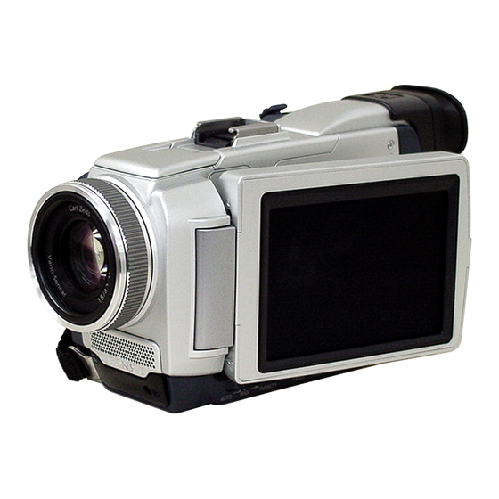
DCR-TRV40/TRV40E/
Photo: DCR-TRV50E
BLOCK DIAGRAMS
BLOCK DIAGRAMS
FRAME SCHEMATIC DIAGRAMS
FRAME SCHEMATIC DIAGRAMS
SCHEMATIC DIAGRAMS
SCHEMATIC DIAGRAMS
Mounted parts location ............................. Pages 4-98 to 4-99
Electrical parts list ................................... Pages 6-18 to 6-25
DIGITAL VIDEO CAMERA RECORDER
TRV50/TRV50E
RMT-811
LEVEL
US Model
Canadian Model
AEP Model
East European Model
DCR-TRV40E/TRV50E
UK Model
Australian Model
DCR-TRV40/TRV40E/TRV50/TRV50E
Hong Kong Model
DCR-TRV40/TRV50E
Tourist Model
DCR-TRV40/TRV40E
Korea Model
Chinese Model
PRINTED WIRING BOARDS
PRINTED WIRING BOARDS
ADJUSTMENTS
ADJUSTMENTS
REPAIR PARTS LIST
REPAIR PARTS LIST
2
DCR-TRV50
DCR-TRV50E
E Model
DCR-TRV40
DCR-TRV40E
Advertisement
Table of Contents

Related Manuals for Sony Handycam DCR-TRV50E


Summarization of Contents
Service Manual: Service Notes and Self-Diagnosis
Self-Diagnosis Functions and Code Table
Explains self-diagnosis functions, display modes, and provides a table of error codes for troubleshooting camcorder issues.
Service Manual: Camcorder Disassembly Procedures
LCD Section (PD-165 Board) Disassembly Steps
Step-by-step instructions for disassembling the LCD section, including part removal and handling precautions.
Service Manual: System Block Diagrams
Overall System Block Diagrams Overview
Presents overall system block diagrams illustrating the interconnections of major camcorder components for system understanding.
Service Manual: Schematic Diagrams and Printed Wiring Boards
Frame Schematic Diagrams Overview
Provides frame schematic diagrams for various circuit boards, detailing component layout and circuit connections.
Service Manual: Camcorder Adjustment Procedures
Camera Section Adjustment Procedures
Covers detailed adjustment procedures for camera functions like white balance, focus, optical alignment, and image settings.
Service Manual: Camcorder Repair Parts List
Exploded Views of Camcorder Sections
Detailed exploded views of different camcorder sections, illustrating part locations and providing part numbers for replacement.
Need help?
Do you have a question about the Handycam DCR-TRV50E and is the answer not in the manual?
Questions and answers