
Related Manuals for ABB 500NMD02


Summarization of Contents
Introduction to EDS500 Manual
1.1 About the Manual EDS500 Series
Details the composition and parts of the EDS500 series manual.
1.2 References
Lists supporting documents and references for the EDS500 series.
Safety Instructions
2.1 Introduction to Safety
Introduction to the safety chapter, emphasizing pre-mounting and commissioning checks.
2.2 Safety Indication Symbols
Explains the meaning and usage of safety symbols in the documentation and on devices.
2.3 Applicable Standards and Directives
Lists relevant standards and directives for installation and operation compliance.
2.4 Qualified Personnel Requirements
Defines the necessary qualifications for personnel handling EDS500 series devices.
2.5 Intended Use of Product
Specifies the intended use of the EDS500 series products for safe and compliant operation.
2.6 Warnings and Cautions
Provides critical warnings and cautions for safe handling, mounting, and operation of devices.
System Concept Overview
3.1 Device Family
Introduces the EDS500 device family and its design for process data communication.
3.2 Network Structures
Describes various network structures that can be realized with EDS500 devices.
3.3.1 Remote Control Protocols and Protocol Integration
Explains support for TCP/IP and serial protocols like IEC 60870-5-104.
3.3.2 Monitor and Interface Dependencies
Covers device monitoring, IP address checking, and interface dependency functions.
3.3.3 Switching and Spanning Tree
Details the Layer 2/3 switching capabilities and network loop prevention protocols.
3.3.4 Virtual Local Networks (VLANs)
Explains the use of VLANs for splitting physical networks into logical segments.
3.3.5 IP Routing
Describes the support for IP routing to create or participate in routed environments.
3.3.6 SNMP
Details the Simple Network Management Protocol for remote monitoring and control.
3.3.7 Syslog
Explains the Syslog protocol for transmitting log entries in an IP network.
3.3.8 Alarm System
Describes the three-level alarm model for device status indication.
3.3.9 SSH-Telnet Console
Covers access to a command interpreter via SSH and Telnet for configuration.
3.3.10 Web Interface
Describes the web server for a user-friendly interface for configuration and monitoring.
3.3.11 RADIUS
Explains RADIUS protocol for authentication of logins to network devices.
Device Description Details
4.1 Compact Device 500NMD01
Detailed description, overview, and data for the 500NMD01 compact device.
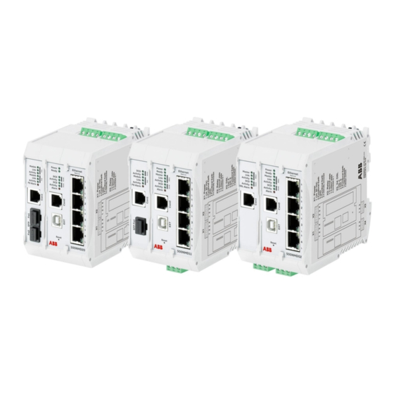
4.2 Compact Device 500NMD02
Detailed description, overview, and data for the 500NMD02 compact device.
4.3 Compact Device 500NMD11
Detailed description, overview, and data for the 500NMD11 compact device.
4.4 Compact Device 500NMD20
Detailed description, overview, and data for the 500NMD20 compact device.
4.5 Compact Device 500NMD30
Detailed description, overview, and data for the 500NMD30 compact device.
4.6 General Data
Provides general technical data, standards, and environmental conditions for EDS500 devices.
4.7 Connections
Details electrical specifications and pin allocations for various device interfaces.
4.7.1 Ethernet Interfaces (Port1 - Port4)
Specifies electrical details, protocol, data rates, and connectors for Ethernet ports.
4.7.2 SFP Interfaces (Fo1 - Fo2)
Details SFP interfaces, optical SFPs, cable types, and warnings for laser class.
4.7.3 DSL Interfaces (X3 - X4)
Describes SHDSL interface specifications, protocols, data rates, and pin allocations.
4.7.4 Serial Interfaces RS-232 (Con0 - Con1)
Details serial interface specifications, data rates, and pin allocations for RS-232.
4.7.5 Power Connector (X1)
Specifies power supply input voltage, consumption, and connector details.
4.7.6 Alarm-Relay (X2)
Describes the potential-free alarm output relay, its type, and pin allocation.
4.7.7 Extension Interface (EXT)
Details the proprietary expansion bus for configuration parameter storage and backup.
4.8 Display Elements
Explains the meaning of various LEDs on the devices for status indication.
4.9 Controls
Details the controls available on the device, such as the reset button.
4.9.1 Reset Button
Explains the function and usage of the reset button for device restart and configuration loading.
4.10 Accessories
Lists available accessories, including optical SFP modules and power supplies.
4.10.1 Optical SFP Modules
Lists ordering information for various optical SFP modules with different ranges.
4.10.2 Other Accessories
Lists other accessories such as line transformers and configuration adapters.
Need help?
Do you have a question about the 500NMD02 and is the answer not in the manual?
Questions and answers