Table of Contents
Advertisement
E3265
REV D 8/9/13
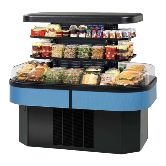
IMSS60, IMSS84 & IMSS120 MODELS
INSTALLATION & OPERATIONS MANUAL
KEEP THIS MANUAL FOR FUTURE REFERENCE
Engineering and technical data are subject to change without notice.
FEDERAL INDUSTRIES
Toll Free 1(800) 356-4206
IMSS E3265
FEDERAL INDUSTRIES
P.O. Box 290
WI Phone (608) 424-3331
Belleville, WI 53508
Fax: (608) 424-3234
- 1 -
Advertisement
Table of Contents

Related Manuals for FEDERAL INDUSTRIES IMSS60SC


Summarization of Contents
INTRODUCTION
SERIAL NUMBER
Record the model and serial numbers of the case for easy reference.
WARNING LABELS & SAFETY INSTRUCTIONS
NOTICE TO EMPLOYERS
Ensure all personnel are familiar with safety information and procedures for case installation, use, or service.
PRE-INSTALLATION PROCEDURES
Inspection For Shipping Damage
Inspect all cartons and crates for damage upon arrival and file freight claims immediately.
INSTALLATION INSTRUCTIONS
Locating The Display Case
Select a location free from direct sun, heat sources, and air disturbances for optimal performance.
Electrical Connection
Details on connecting the display case to the power supply, including types of connections and safety precautions.
Removing Case From Shipping Skid
Instructions for safely removing the display case from its shipping skid and securing it.
Removing Packaging Material
Guidance on removing bubble wrap and packing material from shelves and components.
Leveling The Case
Steps to ensure the display case is level for proper defrost water drainage to the condensate pump.
Sealing Unit To The Floor
Procedure for sealing the unit to the floor for NSF approved installation after positioning.
Base Panel Removal
Instructions for removing side and end panels for IMSS60 and IMSS84 models.
Base Component Layout Self Contained IMSS60 & IMSS84
Diagram illustrating the component layout for self-contained IMSS60 and IMSS84 models.
Base Component Layout Remote IMSS60 & IMSS84
Diagram illustrating the component layout for remote IMSS60 and IMSS84 models.
Base Component Layout Self Contained IMSS120
Diagram illustrating the component layout for self-contained IMSS120 models.
Condensate Evaporator Installation
Details on the condensate evaporator for standard self-contained models, including its function and maintenance.
Condensate Pump Details
Information on the optional condensate pump, its function, maintenance, and installation notes.
Shelf Installation
Instructions for installing and adjusting the LED-equipped metal shelves and their brackets.
OPERATING INSTRUCTIONS
User Controls Overview
Overview of the user interface controls, including power, lights, and electronic control settings.
Power Switch Operation
Description of the main power switch that controls the entire unit, including evaporator and lights.
Light Switch Operation
Description of the light switch that turns the interior lights on and off.
Electronic Control System
Details on the electronic control system, including the temperature control knob and indicator lights.
Temperature Control Knob Function
Explanation of how the temperature control knob adjusts the display interior temperature from OFF to COLD.
Indicator Lights Explained
Explanation of Cooling, Defrost, and Alarm indicator lights and their meanings.
Initial Start-Up Procedure
Steps for powering on the unit and setting the initial temperature control for startup.
Product Loading Guidelines
Guidelines for properly loading product into the display case to ensure optimal airflow and temperature.
MAINTENANCE
Cleaning Condenser Coil
Procedure for cleaning the condenser coil to maintain refrigeration performance and prevent compressor failure.
CLEANING INSTRUCTIONS
Acrylic Air Deflector Cleaning
Special washing procedures for the clear acrylic air deflector to prevent hazing and yellowing.
Daily Cleaning Procedures
Instructions for daily cleaning procedures, emphasizing electrical component safety.
Weekly Cleaning Procedures
Detailed instructions for weekly cleaning of the unit, including interior and exterior components.
SERVICE INFORMATION
Pre-Service Checklist
Checklist to diagnose and resolve common case performance issues before calling for service.
Special Service Situations
Information on handling special service situations, including refrigerant evacuation and moisture/liquid issues.
CONTROL OPERATION
Electronic Control System
Details on the Invensys – Ranco model E72R temperature control and its factory-set parameters.
Control Operation Explained
Explanation of the control's operation using two sensors and critical sensor locations.
Defrost Cycle Modes
Description of the programmed and 'On demand' defrost cycles initiated by the Ranco control.
Control Factory Settings
Chart detailing the factory default control parameters for configuration, set-points, display, and defrost.
Control Display Function
Information about the control display located in the unit base, showing discharge temperature.
Maximum Run Timer
Explanation of the maximum run timer feature that limits compressor runtime if cut-out is not reached.
REFRIGERATION OPERATION
Self Contained Models Operation
Operation details for self-contained models, including R404A charge and condenser air cooling requirements.
Remote Models Operation
Instructions for setting pressure controls on remote models using pressure gauges and ensuring proper operation.
PARTS LIST
Replacement Parts List
List of replacement parts categorized by refrigeration system and electrical components for different models.
Miscellaneous Components List
List of miscellaneous components such as display decks, shelves, and deflectors.
CASE WIRING DIAGRAMS
Self Contained IMSS60SC (Before 5/23/12) Wiring
Wiring diagram for Self Contained IMSS60SC models manufactured before May 23, 2012.
Self Contained IMSS84SC (Before 5/23/12) Wiring
Wiring diagram for Self Contained IMSS84SC models manufactured before May 23, 2012.
Remote IMSS60R (Before 5/23/12) Wiring
Wiring diagram for Remote IMSS60R models manufactured before May 23, 2012.
Remote IMSS84R (Before 5/23/12) Wiring
Wiring diagram for Remote IMSS84R models manufactured before May 23, 2012.
Self Contained IMSS60SC (After 5/23/12) Wiring
Wiring diagram for Self Contained IMSS60SC models manufactured after May 23, 2012.
Self Contained IMSS84SC (After 5/23/12) Wiring
Wiring diagram for Self Contained IMSS84SC models manufactured after May 23, 2012.
Self Contained IMSS120SC Wiring
Wiring diagram for Self Contained IMSS120SC models.
Remote IMSS60R (After 5/23/12) Wiring
Wiring diagram for Remote IMSS60R models manufactured after May 23, 2012.
Remote IMSS84R (After 5/23/12) Wiring
Wiring diagram for Remote IMSS84R models manufactured after May 23, 2012.
Remote IMSS120 Wiring
Wiring diagram for Remote IMSS120 models.
Need help?
Do you have a question about the IMSS60SC and is the answer not in the manual?
Questions and answers