Table of Contents
Advertisement
E3265
REV D 8/9/13
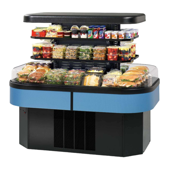
IMSS60, IMSS84 & IMSS120 MODELS
INSTALLATION & OPERATIONS MANUAL
KEEP THIS MANUAL FOR FUTURE REFERENCE
Engineering and technical data are subject to change without notice.
FEDERAL INDUSTRIES
Toll Free 1(800) 356-4206
IMSS E3265
FEDERAL INDUSTRIES
P.O. Box 290
WI Phone (608) 424-3331
Belleville, WI 53508
Fax: (608) 424-3234
- 1 -
Advertisement
Table of Contents

Related Manuals for FEDERAL INDUSTRIES IMSS60 Series


Summary of Contents for FEDERAL INDUSTRIES IMSS60 Series
- Page 1 E3265 REV D 8/9/13 FEDERAL INDUSTRIES IMSS60, IMSS84 & IMSS120 MODELS INSTALLATION & OPERATIONS MANUAL KEEP THIS MANUAL FOR FUTURE REFERENCE Engineering and technical data are subject to change without notice. FEDERAL INDUSTRIES P.O. Box 290 Belleville, WI 53508 Toll Free 1(800) 356-4206...
-
Page 2: Table Of Contents
CONTENTS INTRODUCTION ............................3 WARNING LABELS & SAFETY INSTRUCTIONS ................4 PRE-INSTALLATION PROCEDURES ....................5 INSPECTION FOR SHIPPING DAMAGE ................5 INSTALLATION INSTRUCTIONS......................5 LOCATING THE DISPLAY CASE ..................5 ELECTICAL CONNECTION ....................5-6 PERMANENT CONNECTED ..................... 5-6 STANDARD BASE ELECTRICAL CONNECION ............5-6 TOP ELECTRICAL CONNECION .................. -
Page 3: Introduction
INTRODUCTION Thank you for purchasing a Federal Industries display case. This manual contains important instructions for installing and servicing the IMSS Models. A repair parts list and wiring diagrams are also included in the manual. Read all of these documents carefully before installing or servicing your case. -
Page 4: Warning Labels & Safety Instructions
WARNING LABELS & SAFETY INSTRUCTIONS This is the safety-alert symbol. When you see this symbol on your case or in the manual, be alert to the potential for personal injury or damage to your equipment. Be sure you understand all safety messages and always follow recommended precautions and safe operating procedures. -
Page 5: Pre-Installation Procedures
PRE-INSTALLATION PROCEDURES Inspection For Shipping Damage You are responsible for filing all freight claims with the delivering truck line. Inspect all cartons and crates for damage as soon as they arrive. If damage is noted to shipping crates, cartons, or if a shortage is found, note this on the bill of lading (all copies) prior to signing. -
Page 6: Top Electrical Connecion
Section” of this manual for panel removal instructions. Remove electrical box cover to access electrical connection. PERMANENT CONNECTION TERMINAL BLOCK OR WIRE PERMANENT CONNECTION ELECTRICAL BOX COVER Optional Top Electrical Connection: The electrical connection box is accessible on the top of the case for ceiling drop electrical connection. Remove electrical box cover to access electrical connection. -
Page 7: Removing Case From Shipping Skid
Removing Case From Shipping Skid CAUTION Do not push against the clear acrylic deflector around the sides and nose. Doing so can cause the acrylic to break. Do not lift or push on the top canopy located on top of the case. Doing so can permanently damage the tower frame. -
Page 8: Sealing The Unit To The Floor
Sealing Unit To The Floor After the unit is positioned and the leg levelers are turned out, the unit needs to be sealed to the floor for NSF approved installation. Base Panel Removal IMSS60 and IMSS84 Panels DANGER: Electric shock hazard. Do not operate unit with panels removed. Panels must be in place when operating the case. -
Page 9: Base Panels Removal Imss120
Panels must be in place when operating the case. LOUVERS RIGHT SIDE PANEL REMOVE THIS PANEL LEFT SIDE PANEL TO CLEAN CONDENSER CONTROLS (3) SIDE PANEL RETAINER SCREWS (3) TABS SIDE PANEL SLOT LOUVERS REMOVE THIS PANEL TO CLEAN CONDENSER Side Panels 1. -
Page 10: Base Component Layout Imss60 & Imss84
60.41 IMSS60 84.41 IMSS84 7/8 FLOOR ELECTRICAL CONNECTION LOCATION DATA PLATE LOCATION 4. 2 LIGHT POWER SUPPLY QUANITY MAY DIFFER BETWEEN MODELS 40.4 POWER CONNECTION CONDENSATE ELECTRICAL EVAPORATOR OR OPTIONAL CONDENSATE PUMP CONTROL 4. 2 PANEL LOCATION PULL OUT SIGHT GLASS CONDENSING UNIT Base Component Layout Remote IMSS60 &... -
Page 11: Base Component Layout Imss120
120.41 CONDENSATE 7/8 FLOOR ELECTRICAL EVAPORATOR CONNECTION LOCATION OR OPTIONAL LIGHT POWER SUPPLY WIRING DIAGRAM CONDENSATE PUMP DATA PLATE LOCATION 12.1 40.41 POWER CONNECTION CONTROL PANEL LOCATION CASTERS (6) PULL OUT 17.1 BASE FLOOR LEG LEVELERS (6) CONDENSING UNIT CONTROL ACCESS PLATE SIGHT GLASS DISPLAY... -
Page 12: Condensate Pump
NOTICE: During normal defrost cycles, steam from the condensate evaporator may be visible around the case. The standard Self Contained case is furnished with an electric condensate evaporator. Plumbing connections are not required. The condensate evaporator can be removed from the case and the condensate drain can be plumbed to a drain to conserve energy if desired. -
Page 13: Shelves
Shelves The IMSS has solid metal shelves with LED lighting as standard. There are (4) brackets required for each shelf (2) long brackets and (2) short brackets. The long brackets are for the long side of case and the short brackets are at the short end of case. - Page 14 3. Set the shelf on to the brackets and place the bracket retainer clip into slots on shelf. 4. Push shelf light cords into plastic shelf cord retainer clip located on inside of shelf bracket. 5. Remove the cap from the appropriate female light sockets. 6.
-
Page 15: Operating Instructions
OPERATING INSTRUCTIONS User Controls ELECTRONIC CONTROL POWER SWITCH COOLING INDICATOR DEFROST INDICATOR ALARM INDICATOR TEMPERATURE LIGHT SWITCH CONTROL KNOB Power Switch The unit has a power switch that turns off power to the entire unit, including the condensate evaporator and the lights. This switch is located behind a lift up panel on the unit base. -
Page 16: Initial Start Up
Initial Start-Up After all the checks outlined in the installation section of this manual have been made, the case is ready to be put into service. Turn on the Power at the breaker box and flip the Power Switch and Light Switch on unit to the on position. At start up from a warm unit, it is recommended that the temperature control is set at a warm setting, such as 1 on the dial. -
Page 17: Maintance
Maintance Cleaning Condenser Coil NOTICE: Condenser coil must be cleaned a minimum of twice per month to insure proper refrigeration performance and prevent compressor failure. Failure to clean condenser coil will void condenser warranty. It is very important that the Condenser coil is cleaned twice per month to insure proper refrigeration performance and to prevent compressor failure. -
Page 18: Cleaning Instructions
CLEANING INSTRUCTIONS Acrylic Air Deflector Cleaning NOTICE: Clear acrylic air deflector requires special washing procedures to prevent hazing and yellowing of material. NEVER USE paper towels (wet or dry) for cleaning or drying and never use a dry towel. NEVER USE glass cleaner of any kind. Lightly dust (not wipe) surface with a damp Micro Fiber towel or chamois. -
Page 19: Weekly Cleaning
Weekly Cleaning NOTICE: Avoid splashing or soaking any electrical components with water to prevent electrical damage to the case. NOTICE: Shut off lights and power switches and remove all products from case. Allow sufficient time for the unit to reach room temperature before proceeding with cleaning. -
Page 20: Service Information
Service problems or request for repair parts from authorized service agencies, trained service personnel, or owners should be referred to: TECHNICAL SERVICE DEPARTMENT Federal Industries P.O. Box 290 Belleville, WI 53508 Toll Free: (800) 356-4206 / WI Phone (608) 424-3331... -
Page 21: Pre-Service Checklist
Pre-Service Checklist You may avoid the cost and inconvenience of an unnecessary service call by first reviewing this checklist of frequently encountered situations that can cause unsatisfactory case performance. CAUTION: Before servicing case, turn off power at the main breaker of fuse box. -
Page 22: Special Service Situations
If moisture or liquid is observed around or under a Federal Industries case, an immediate investigation should be made by qualified personnel to determine the source of the moisture or liquid. -
Page 23: Sale & Disposal
SALE & DISPOSAL If you the owner sells or gives away this Federal Industries case it is the owner’s responsibility to make sure that all safety labels and the Installation-Service Manual are included with it. If you need replacement labels or manuals, Federal Industries will provide them free of charge. - Page 24 Model IMSS120SC IMSS120R REFRIGERATION CHARGE 9.5 pounds (R-404A) POWER SUPPY, VOLTS 230 Volts 230 Volts Frequency 60 Hertz 60 Hertz Phase 1 Phase 1 Phase Number of Wires 2 + GND 2 + GND AMPS VOLTS AMPS VOLTS Compressor Condenser Fan (QTY 2) .5 ea Evaporator Fan Motor (QTY 6) 0.15 ea.
-
Page 25: Control Operation
Control parameter changes can only be made by downloading a new set of parameters via a program chip supplied by Federal Industries. The pre set control parameters are listed on the chart in the Settings Chart below. -
Page 26: Control Factory Setting
The control parameters are set at the factory and cannot be manually changed in the field. Control parameter changes can only be made by downloading a new set of parameters via a program chip supplied by Federal Industries E3380 AS OF:... -
Page 27: Control Display
Control Display The control display is located in the unit base. It is programmed to display the current discharge temperature from the control sensor located inside the center tower at the top. Maximum Run Timer, Before 5/23/12 Only The unit is equipped with a maximum run timer that is preset at the factory for 60 minutes on and 10 minutes off. - Page 28 low pressure switch must be wired in series with the compressor power supply as shown in diagram below. 1. Mount condensing unit indoors as close to the remote display case as practical. The refrigeration line should be as short as possible and must not exceed 30 feet. 2.
-
Page 29: Replacement Parts
PARTS LIST REPLACEMENT PARTS Refrigeration System IMSS60 IMSS84 IMSS120 Condensing Unit (Self Contained) 30-19025 30-19025 30-19675 Evaporator Coil Left/ Right 33-18811-L/33-18811-R 33-19287-L/33-19287-R 33-19647-L/33-19647-R Expansion Valve TXV 32-19408 32-19408 32-19750 Sight Glass 32-54011 32-54011 32-54011 Refrigerant Filter/Drier 32-19067 32-19067 32-19067 Refrigeration Solenoid Valve (Remote) 32-19153 32-19153 32-19153... -
Page 30: Wiring Drawing
Case Wiring Diagrams Self Contained IMSS60SC BEFORE 5/23/12 IF OPTIONAL CONDENSATE PUMP OR 91-19453 12/19/11 IMSS60SC & ECSS60SC OPTIONAL CONDENSATE PAN ARE NOT USED CONDENSATE PUMP DISCARD WIRES B(22), R(23),G(24), R(22) R(23) POWER SUPPLY B/BL G(24) B/BL TOP LAMP ECSS ONLY B/BL B/BL B/BL... - Page 31 Self Contained IMSS84SC BEFORE 5/23/12 IF OPTIONAL CONDENSATE PUMP OR 91-19451 9/28/11 IMSS84SC COLOR CODE CONDENSATE PAN ARE NOT USED B = BLACK BL = BLUE G = GREEN DISCARD WIRES B(22), R(23),G(24), B/BL W = WHITE Y = YELLOW R = RED TOP LAMP OPTIONAL...
- Page 32 Remote IMSS60R BEFORE 5/23/12 91-19454 1/2/12 IMSS60R & ECSS60R OPTIONAL CONDENSATE HEATER PAN POWER SUPPLY R(23) B/BL B(22) B/BL G(24) TOP LAMP ECSS ONLY B/BL B/BL B/BL SHELF LAMP TOP LAMP COLOR CODE B/BL B/BL B/BL B/BL B = BLACK BL = BLUE SHELF LAMP SHELF LAMP...
- Page 33 Remote IMSS84R BEFORE 5/23/12 91-19452 1/2/12 IMSS84R COLOR CODE B = BLACK BL = BLUE G = GREEN OPTIONAL CONDENSATE B/BL W = WHITE Y = YELLOW R = RED HEATER PAN TOP LAMP R(23) B(22) B/BL POWER SUPPLY G(24) TOP LAMP POWER SUPPLY B/BL...
- Page 34 Self Contained IMSS60SC AFTER 5/23/12 IF OPTIONAL CONDENSATE PUMP OR 91-19630 5/23/12 IMSS60SC & ECSS60SC OPTIONAL CONDENSATE PAN ARE NOT USED CONDENSATE PUMP DISCARD WIRES B(22), R(23),G(24), R(22) R(23) POWER SUPPLY B/BL G(24) B/BL TOP LAMP ECSS ONLY B/BL B/BL B/BL SHELF LAMP TOP LAMP...
- Page 35 Self Contained IMSS84SC AFTER 5/23/12 IF OPTIONAL CONDENSATE PUMP OR 91-19632 5/23/12 IMSS84SC COLOR CODE CONDENSATE PAN ARE NOT USED B = BLACK BL = BLUE G = GREEN DISCARD WIRES B(22), R(23),G(24), B/BL W = WHITE Y = YELLOW R = RED TOP LAMP OPTIONAL...
- Page 36 Self Contained IMSS120SC L2 N DEFROST PROBE PLUG TEMP PROBE CONTROL BLK/RIB BLK/RIB BLK/RIB POWER EVAP. SWITCH FANS BLK/RIB BLK/RIB BLK/RIB BLK/RIB BLK/RIB LIGHT SWITCH EVAP. DISPLAY PLUG FANS BLK/RIB BLK/RIB HI/LO B/BL PRESS TOP LAMP B/BL B/BL COMPRESSOR SHELF LAMP B/BL B/BL SHELF LAMP...
- Page 37 Remote IMSS60R AFTER 5/23/12 91-19631 5/23/12 IMSS60R & ECSS60R OPTIONAL CONDENSATE HEATER PAN POWER SUPPLY R(23) B/BL B(22) B/BL G(24) TOP LAMP ECSS ONLY B/BL B/BL B/BL SHELF LAMP TOP LAMP COLOR CODE B/BL B/BL B/BL B/BL B = BLACK BL = BLUE SHELF LAMP SHELF LAMP...
- Page 38 Remote IMSS84R AFTER 5/23/12 91-19633 5/23/12 IMSS84R COLOR CODE B = BLACK BL = BLUE OPTIONAL CONDENSATE G = GREEN B/BL W = WHITE Y = YELLOW R = RED HEATER PAN TOP LAMP R(23) B(22) B/BL POWER SUPPLY G(24) TOP LAMP POWER SUPPLY B/BL...
- Page 39 Remote IMSS120 L2 N DEFROST PROBE PLUG TEMP PROBE CONTROL BLK/RIB BLK/RIB BLK/RIB POWER EVAP. SWITCH FANS BLK/RIB BLK/RIB BLK/RIB BLK/RIB BLK/RIB LIGHT SWITCH EVAP. DISPLAY PLUG FANS BLK/RIB BLK/RIB REFRIGERATION SOENOID B/BL TOP LAMP CAP EXTRA BLACK WIRE B/BL B/BL SHELF LAMP B/BL...
Need help?
Do you have a question about the IMSS60 Series and is the answer not in the manual?
Questions and answers