
Related Manuals for Pneumatech PB Series


Summary of Contents for Pneumatech PB Series
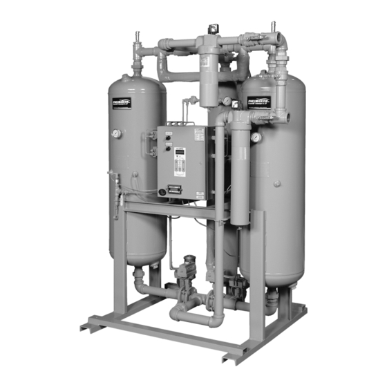
- Page 1 EACTIVATED RYERS PE SERIES/EE SERIES/PB SERIES Owner’s Manual Printed in U.S.A. Publication No. OM-A-10E April 2004...
- Page 2 To receive Extended Warranty, you must regis- ter on line at: www.pneumatech.com. Doing this will extend the warranty to 24 months from date of shipment from Company’s factory. See back page for actual Warranty details. DATE OF PURCHASE MODEL SERIAL NO.
-
Page 3: Table Of Contents
TABLE OF CONTENTS Page General Information ............Receiving –... - Page 4 PB Series Heat Reactivated Blower Purge Air Dryer Maintenance..... General............Daily .
-
Page 5: General Information
GENERAL INFORMATION SAFETY INSTRUCTIONS The Pneumatech Drying System is designed to remove moisture from compressed air. When using air compressors and compressed air When properly installed, the unit requires little accessories, basic safety rules and precautions must maintenance or adjustment. -
Page 6: Disclaimer Of Warranty
DISCLAIMER OF WARRANTY SECURE DRAIN LINES Fasten drain lines from prefilter/separator to floor or If this unit is used to produce breathing air, the special drain. Pressurized air will periodically pass through equipment and precautions expressed in OSHA 29 CFR drain lines, which will cause an unsecured line to 1910.134 for specifications of the necessary equipment whip and may cause bodily injury. -
Page 7: Desiccant Replacement Procedures
DESICCANT REPLACEMENT PROCEDURES DRAINING PROCEDURE Pneumatech uses Activated Alumina Grade A desiccant for all standard heat reactivated air dryers. Dryers up to The desiccant can be removed by the two methods listed 1500 SCFM are factory filled with desiccant. Dryers below. -
Page 8: Installation & Operation
INSTALLATION & OPERATION FIGURE 1 — COMPRESSED AIR SYSTEM RECOMMENDED INSTALLATION FLOW DIAGRAM Pub. No. OM-A-10E — April 2004... -
Page 9: Pe & Ee Series Heat Reactivated Air Dryer Installation & Operation
PE & EE SERIES HEAT REACTIVATED AIR e. Prior to start-up, check the heater element resistance. The element (phase) to ground should DRYER INSTALLATION & OPERATION exceed the resistance value by 20 megohms. If this value is not indicated, energize the heater at low voltage to drive the moisture from the General element insulation. -
Page 10: Adjustments & Settings
“ADVANCE” push button is disabled whenever the INTRODUCTION timing is stopped by an inhibit switch. GENERAL: The Pneumatech DMP controller is a microprocessor controlled, ten (10) channel sequence timer with LCD and LED display features. The DMP controller consists of the main control unit and the remote LCD, LED and I/O module. - Page 11 LOW PRESSURE: All heated regenerative dryers b. The high temperature set point to be adjusted will are supplied with Low Pressure Switch Inhibit. When be displayed on the LCD. Use the “TEMP the low pressure is detected, all timing functions stop DISPLAY”...
-
Page 12: Sequence Of Operation
FAIL TO SHIFT: The fail to shift inhibit will be With the power switch in the ON position at energized if the inhibit switch remains closed for 30 time equal to 0.0 hrs., the left tower air inlet valve is minutes beyond the normal cycle. -
Page 13: Shutdown Procedure
ZERO 240 MINUTES 480 MINUTES LEFT TOWER SWITCHING RIGHT TOWER SWITCHING LEFT TOWER REGENERATING RIGHT TOWER REGENERATING HEATER DEMAND CYCLE LEFT TOWER DEPRESSURIZING (OPT.) RIGHT TOWER DEPRESSURIZING (OPT.) ZERO 240 MINUTES 480 MINUTES R TOWER R TOWER L TOWER L TOWER TIMING STAGE: HEATING COOLING... - Page 14 TYPICAL PE SERIES FLOW DIAGRAM AIR OUTLET PILOT AIR LINE EX (SLIGHT BLEED) CLOSED OPEN CLOSED OPEN DRYING REGEN FLOW FLOW CLOSED CLOSED OPEN OPEN CLOSED INLET PRESSURE VESSEL 16. HEATER CONTROL THERMOSTAT AIR INLET VALVE 17. OVER TEMPERATURE THERMOSTAT AIR OUTLET CHECK VALVE 18.
-
Page 15: Pb Series Heat Reactivated Blower Purge Air Dryer Installation & Operation
PB SERIES HEAT REACTIVATED BLOWER e. Prior to start-up, check the heater element resistance. Element (phase) to ground should PURGE AIR DRYER INSTALLATION & exceed the resistance value by 20 megohms. If this value is not indicated, energize the heater at OPERATION low voltage to drive the moisture from the element insulation. -
Page 16: Adjustments & Settings
Slowly open the dryer outlet isolation valve to With the power switch in the ON position at pressurize the downstream system. time equal to 0.0 hrs., the left tower air inlet valve is open to allow the air to pass through the left tower. The 10. -
Page 17: Dry Air Sweep
Dry Air Sweep If the compressed air system has been piped with a bypass around the dryer, then In order to maintain constant dewpoint, the Pneumatech the following should be completed: dryer uses a dry air sweep during the cool down cycle. - Page 18 TYPICAL PB SERIES FLOW DIAGRAM AIR OUTLET PILOT AIR LINE EX (SLIGHT BLEED) CLOSED OPEN OPEN CLOSED REGEN DRYING FLOW FLOW CLOSED CLOSED OPEN OPEN CLOSED INLET PRESSURE VESSEL 19. PURGE ORIFICE ASSEMBLY AIR INLET VALVE 20. PURGE ADJUSTMENT PRESSURE GAUGE PURGE FLOW CHECK VALVE 22.
-
Page 19: Maintenance
MAINTENANCE PE & EE SERIES HEAT REACTIVATED AIR Three Months Every three (3) months, close the purge adjusting DRYER MAINTENANCE valve momentarily to check for any leaks in the inlet and/or check valves indicated by air coming through the exhaust mufflers. Check the prefilter and afterfilter elements for excessive clogging or possible damage. -
Page 20: Mufflers
Mufflers Monthly Purge mufflers are installed to reduce the noise level. The Check the pilot air filter element. Replace if mufflers tend to plug up and increase back pressure over necessary. time due to oil carryover and contaminants from Check the blower intake filter. Replace if necessary. compressor, or due to desiccant dust at the initial start-up. -
Page 21: Dewpoint Display Key Functions
DEWPOINT DISPLAY KEY FUNCTIONS OPEN SENSOR CONDITION DIGITAL DISPLAY KEY FUNCTIONS When message oPEn1 is displayed, the dewpoint sensor BUTTON is likely to be disconnected from the hygrometer. -73.5F SETPOINT LIMIT INDICATION SP1 SP2 Prog. BUTTON Setpoint limit message is the flashing number within PROGRAM operating range of the hygrometer. - Page 22 FIGURE 6 — DEWPOINT DISPLAY CONTROL WIRING Pub. No. OM-A-10E — April 2004...
-
Page 23: Options Listing With Explanation
PLC Controller is standard on PB series Blower Purge Calibration: To maintain accuracy, replace the probe dryers and with Pneumatech’s Pulse Purge Regeneration every two years. option. It can also be added to control the operation of Probe Replacement: Turn the normal/demand selector standard regenerative dryers. -
Page 24: Dewpoint Demand Control "Dpd
DEWPOINT DEMAND CONTROL “DPD” PULSE PURGE REGENERATION (PPR) WITH DEWPOINT DEMAND (DPD) The Dewpoint Demand control is an energy saver that can extend the drying cycle without purging, during periods of (PE & EE Series only) lower moisture loads. The Dewpoint Demand system offers, in one compact package, the utmost in flexibility Pulse Purge Regeneration systems use the same NEMA and accuracy sensing the actual dewpoint of the outlet air. -
Page 25: Troubleshooting
TROUBLESHOOTING Table 1 — Troubleshooting Guide for Regenerative Dryers Symptoms Cause Remedy A. Elevated Dewpoint. 1. Low purge flow. 1. Reset purge pressure at the recommended pressure. 2. Low inlet pressure. 2. Recalculate purge pressure setting from the chart. 3. Excess moisture carryover. 3. -
Page 26: Pub. No. Om-A-10E — April
Table 1 — Troubleshooting Guide for Regenerative Dryers, continued Symptoms Cause Remedy D. Excessive flow through mufflers. 1. Check valves leaking. 1. Repair or replace faulty check valves. NOTE: To test for leaking, check valves during regeneration cycle, shut the purge adjusting valve. - Page 27 Table 1 — Troubleshooting Guide for Regenerative Dryers, continued Symptoms Cause Remedy L. Tower does not pressurize fully. 1. Inlet pressure low. 1. Calibrate and plot purge pressure and reset. 2. Purge pressure too low. 2. Reset proper purge pressure. 3.
- Page 28 LIMITED WARRANTY Warranties and Limitation of Liability: Pneumatech/ConservAIR (“the Company”) warrants that it will, in its sole discretion, either repair or replace Products and/or Components of Products sold by it which have defects in material or workmanship (covering Components and reasonable labor) provided: (a) Customer notified the Company of any claim of defect in material or workmanship within fourteen (14) months from date of shipment from the Company’s factory or twelve (12) months from the date of initial operation of Product, whichever occurs...
Need help?
Do you have a question about the PB Series and is the answer not in the manual?
Questions and answers