
Related Manuals for Pneumatech PH 55


Summary of Contents for Pneumatech PH 55
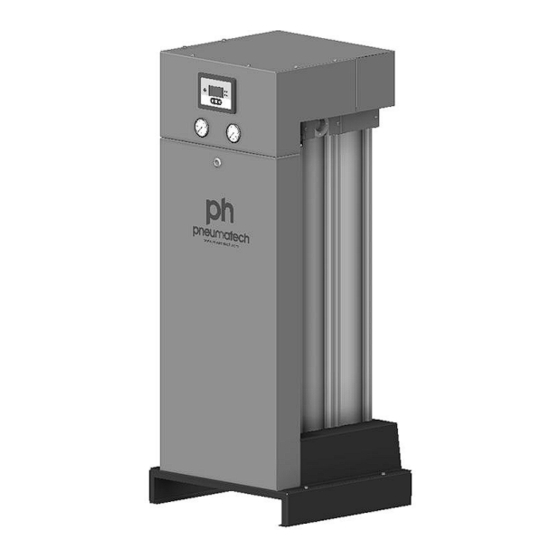
- Page 1 Pneumatech Heatless adsorption air dryers PH 55, PH 75, PH 95, PH 120, PH 140, PH 190, PH 230, PH 275, PH 350, PH 420, PH 550 Instruction book...
- Page 3 Pneumatech Heatless adsorption air dryers PH 55, PH 75, PH 95, PH 120, PH 140, PH 190, PH 230, PH 275, PH 350, PH 420, PH 550 Instruction book Original instructions Copyright notice Any unauthorized use or copying of the contents or any part thereof is prohibited.
-
Page 4: Table Of Contents
Instruction book Table of contents Safety precautions......................5 ........................... 5 AFETY ICONS ......................5 AFETY PRECAUTIONS GENERAL ................... 6 AFETY PRECAUTIONS DURING INSTALLATION ....................7 AFETY PRECAUTIONS DURING OPERATION ................8 AFETY PRECAUTIONS DURING MAINTENANCE OR REPAIR .........................9 ISMANTLING AND DISPOSAL General description...................... 11 ........................ - Page 5 Instruction book ..........................34 UTPUTS MENU ............................35 OUNTERS ........................37 VENT HISTORY MENU 5.10 ............................. 38 EST MENU 5.11 ..........................39 ERVICE MENU 5.12 ......................... 43 ROTECTIONS MENU 5.13 ...........................44 EEK TIMER MENU 5.14 ............................54 NFO MENU 5.15 ........................54 ODIFYING SETTINGS 5.16 ...........................
- Page 6 Instruction book Instructions for use...................... 86 Guidelines for inspection.....................87 Pressure Equipment Directives...................88 Declaration of conformity.................... 89 2920 7111 23...
-
Page 7: Safety Precautions
Instruction book Safety precautions Safety icons Explanation Danger to life Warning Important note Safety precautions, general General precautions All responsibility for any damage or injury resulting from neglecting these precautions, or non-observance of the normal caution and care required for installation, operation, maintenance and repair, even if not expressly stated, will be disclaimed by the manufacturer. -
Page 8: Safety Precautions During Installation
Instruction book Safety precautions during installation Precautions during installation 1. The dryer must only be lifted using suitable equipment and in accordance with the applicable safety regulations. Loose or pivoting parts must be securely fastened before lifting. It is strictly forbidden to dwell or stay in the risk zone under a lifted load. Lifting acceleration and deceleration must be kept within safe limits. -
Page 9: Safety Precautions During Operation
Instruction book 17. If the maximum pressure of the compressor is higher than the design pressure of the dryer, a full flow safety valve must be installed between the compressor and the dryer in order to blow off the excessive pressure. This is done in case the safety valve of the dryer is out of order or blocked. -
Page 10: Safety Precautions During Maintenance Or Repair
Instruction book atmospheric pressure shall be protected by a pressure relieving device or devices as required. 12. Yearly inspect the air receiver. Minimum wall thickness as specified in the instruction book must be respected. Local regulations remain applicable if they are more strict. Also consult following safety precautions: Safety precautions during installation Safety... -
Page 11: Dismantling And Disposal
Instruction book 18. Make sure that all sound-damping material and vibration dampers, e.g. damping material on the bodywork, is in good condition. If damaged, replace with genuine material from the manufacturer to prevent the sound pressure level from increasing. 19. Never use caustic solvents which can damage materials of the air net, e.g. polycarbonate bowls. - Page 12 Instruction book Disposal of other used material Used filters or any other used material (e.g. filter bags, filter media, desiccant, lubricants, cleaning rags, machine parts, etc.) must be disposed of in an environmentally friendly and safe manner, and in line with the local recommendations and environmental legislation. 2920 7111 23...
-
Page 13: General Description
Instruction book General description General description Introduction The air dryers described in this book are heatless adsorption dryers, designed to remove humidity from compressed air for industrial applications. PH dryers are available in a version to reach a pressure dew point down to -20 °C (-4 °F) or down to -40 ˚C (-40 ˚F) and are equipped with a DC1 electronic controller. -
Page 14: Operation
Instruction book PH 230 – Main parts Reference Description Reference Description DC1 controller Silencer Right tower Air outlet Left tower Operation General With its simple construction, the air dryer is both reliable and easy to service. A dryer module basically consists of two towers, containing the adsorption material or desiccant. The desiccant is a very porous grain material, able to adsorb large amounts of water vapor. - Page 15 Instruction book Flow diagram Reference Designation Reference Designation AIR INLET Air inlet Regeneration valve AIR OUTLET Air outlet Left check valve Left desiccant tower Right check valve Right desiccant tower Blow off silencer Left 3–2 valve Regeneration silencer Right 3–2 valve Nozzle Blow off valve Depending on dryer size, the dryer may consist of a single dryer module (see flow diagram) or a...
- Page 16 Instruction book After a preset period (or when triggered by the PDP sensor) the function of the towers is reversed. The fully regenerated tower will now dry the air, while the desiccant in the other tower will be regenerated. By default, the regeneration timer will restart from the beginning of the cycle in case of a power failure during operation or in case the dryer was switched off.
-
Page 17: Electric Diagram
Instruction book Electric diagram The complete electric diagram can be found in the electrical cabinet and in your technical documentation. Drawing number Controller type 9827 2939 00 Graphic controller 2920 7111 23... -
Page 18: Dc1 Controller
Instruction book DC1 controller Control panel Display ON/OFF button LEFT button ENTER button RIGHT button Alarm LED Power On LED Button functions Press any button to light up the display. Button Normal Alarm Selection Alarms Parameters Counters and operation status menu browser editing... -
Page 19: Main Screen
Instruction book Button Normal Alarm Selection Alarms Parameters Counters and operation status menu browser editing service menu ENTER Displays the Cancels Selects the — Returns to — Starts the Returns to the selection pointed menu the selection parameter editing selection menu menu displayed and activates... -
Page 20: Selection Menu
Instruction book Icon Description Rotating arrow Displayed when the dryer is in its working phases. Stationary vertical bars Displayed when the dryer is in the FREEZE status. Stationary square Displayed when the dryer is stopped. The various working phases are: Phase Text displayed on screen Translation... -
Page 21: Alarm Screen
Instruction book Alarm screen When there is an alarm, you will see the following image on your screen: When one or more alarms are active, the alarm screen overrides the main screen. In the upper right area, the current alarm number and the total active alarms number are displayed. -
Page 22: Editing Parameters
Instruction book Module involved Cause Message on the How to clear the Alarm LED status display alarm Service Running hours > Running hours > Perform the Blinking programmed service hours X (X requested service hours A, B = A, B or C) maintenance (A, B or C or C). - Page 23 Instruction book Editor button functions Button Function LEFT • Selects the previous parameter • Decrements the value RIGHT • Selects the next parameter • Increments the value ENTER • Starts the parameter editing • Selects the numerical data digits • Confirms the modified value •...
- Page 24 Instruction book Parameter Parameter name Description Default value Allowed range number PDP control On: The dryer tries to On or Off follow the set point. Off: only display the PDP. The dryer will run at the lowest possible dewpoint. Dewpoint setpoint Fixes the target for the Based on the model Maximum value: -10 °C...
-
Page 25: Graphic Controller
Instruction book Graphic controller General Controller A controller with a graphical screen is available as option for High Efficiency (+) versions, replacing the basic controller. PureLogic controller General description The controller automatically controls and protects the dryer, i.e.: • Keeping the pressure dew point stable •... -
Page 26: Control Panel
Instruction book The power recovery time (the period within which the voltage must be restored to have an automatic restart) can be set between 15 and 3600 seconds or to ‘Infinite’. If the power recovery time is set to ‘Infinite’, the dryer will always restart after a voltage failure, no matter how long it takes to restore the voltage. -
Page 27: Icons Used
Instruction book Reference Designation Function Start button Button to start the dryer. LED (7) lights up indicating that the controller is operative. Icons used Status icons Name Icon Description Stopped/Running When the dryer is stopped, the icon stands still. When the dryer is running, the icon is rotating. Machine control mode Local start/stop Remote start/stop... - Page 28 Instruction book Input icons Icon Description Pressure Temperature Digital input Special protection System icons Icon Description Dryer Frequency converter Drain Filter Motor Failure expansion module Network problem General alarm Menu icons Icon Description 2920 7111 23...
- Page 29 Instruction book Inputs Outputs Alarms (Warnings, shutdowns) Counters Test Settings Service Event history (saved data) Access key/User password Network Set point Info General settings Navigation arrows Icon Description Down 2920 7111 23...
-
Page 30: Main Screen
Instruction book Main screen Control panel Scroll keys Enter key Escape key Function The main screen shows the status of the dryer operation and is the gateway to all functions implemented in the controller. The main screen is shown automatically when the power is switched on and one of the keys is pushed. - Page 31 Instruction book Dryer animation, two and four value views Dryer animation Two value lines Four value lines 2920 7111 23...
- Page 32 Instruction book Text on figures Pressure equalization Menu • Section A shows information regarding the dryer operation (e.g. the Pressure in vessels A and B, the Dryer Pressure Dewpoint, the Dryer Inlet temperature). • Section B shows Status icons. Following icon types are shown in this field: •...
- Page 33 Instruction book Chart views When Chart (High Resolution) is selected, the value of a parameter (in the example, the pressure is selected, but it could have been the PDP as well) is shown per minute. The parameter is selected in the Inputs menu. Each point in the chart is 1 second. The screen shows 4 minutes. The switch button (icon) for selecting other screens is changed into a small chart and is highlighted (active).
-
Page 34: Calling Up Menus
Instruction book When the Chart (Low Resolution) is selected, a chart showing the parameter per day is shown on the main screen. Each point is the average of 1 hour. The screen shows 10 days. The switch button (icon) for selecting other screens is changed into a small chart and is highlighted (active). -
Page 35: Inputs Menu
Instruction book Inputs menu Menu icon, Inputs Function To call up information regarding the actually measured data and the status of some inputs such as the Vessel Pressure. Procedure Starting from the main screen (see Main screen), • Move the cursor to the action button Menu and press the Enter key. Following screen appears: •... -
Page 36: Outputs Menu
Instruction book Text on figure Inputs Pressure vessel A Pressure vessel B Blower pressure Inlet dryer • The screen shows the first items of a list of all inputs with their corresponding icons and readings. Use the scroll button to see the other items in the list. •... -
Page 37: Counters
Instruction book Text on figure Outputs Dryer motor (means the dryer is operating) PDP alarm General shut-down General warning Not triggered Triggered • The screen shows the first items of a list of all outputs with their corresponding icons and readings. - Page 38 Instruction book • Using the Scroll keys, move the cursor to the Counters icon (see above, section Menu icon). • Press the Enter key. Following screen appears: Text on figure Counters Running hours dryer Loaded hours dryer Actual state time Programmed state time Reset The screen shows a list of all counters with their actual readings.
-
Page 39: Event History Menu
Instruction book • Regeneration cycles vessel B: integer that counts how many cycles vessel B has performed. • Standby time: shows how long the dryer has been in standby mode since the last reset of the energy counters. This counter will not be reset when the standby state has ended and a vessel switch is performed. -
Page 40: Test Menu
Instruction book • Scroll through the items to select the desired shutdown or emergency stop event. • Press the Enter key to find the date, time and other data reflecting the status of the dryer when that shutdown or emergency stop occurred. 5.10 Test menu Menu icon, Test Function... -
Page 41: Service Menu
Instruction book Text on figure Test Depressurize vessels • A red selection bar is covering the item Depressurize vessels. Press the Enter key to depressurize the vessels. 5.11 Service menu Menu icon, Service Function • To reset the service plans which are carried out. •... - Page 42 Instruction book • Using the Scroll keys, move the cursor to the Service icon (see above, section Menu icon). • Press the Enter key. Following screen appears: Text on figure Service Overview Service plan Next service History • Scroll through the items to select the desired item and press the Enter key to see the details as explained below.
- Page 43 Instruction book Overview Text on figure Overview Running Hours (green) Real Time hours (blue) Example for service level (A): The figures at the left are the programmed service intervals. For Service interval A, the programmed number of running hours is 4000 hours (upper row, green) and the programmed number of real time hours is 4380 hours, which corresponds to six months (second row, blue).
- Page 44 Instruction book Text on figure Service plan Level Running hours Real time Next Service Text on figure Next service Level Running hours Actual In the example above, the A Service level is programmed at 4000 running hours, of which 8 hours have passed.
-
Page 45: Protections Menu
Instruction book Service level, Running hours or Real time hours), use the Scroll keys to select the desired action and press the Enter key. 5.12 Protections menu Menu icon, Protections Function To call-up the protections. Before resetting a warning or shut down message, always remedy the problem. Frequently resetting these messages without remedying may damage the dryer. -
Page 46: Week Timer Menu
Instruction book • The screen shows a list of all shutdown and shutdown warning settings and the actual reading. Active alarms are highlighted in yellow. In case of a shutdown, the protection can be reset after remedying. 5.13 Week timer menu Menu icon, Week timer Function •... - Page 47 Instruction book • Press the Enter key on the controller. Following screen appears: Text on figure Week Timer Week Action Schemes Week Cycle Status Week 1 Remaining Running Time The first item in this list is highlighted in red. Select the item requested and press the Enter key on the controller to modify.
- Page 48 Instruction book Text on figure Week Action Schemes Week Action Scheme 1 Week Action Scheme 2 Week Action Scheme 3 Week Action Scheme 4 • A weekly list is shown. Monday is automatically selected and highlighted in red. Press the Enter key on the controller to set an action for this day.
- Page 49 Instruction book Text on figure Monday Modify • A new pop-up window opens. Select an action from this list by using the Scroll keys on the controller. When ready press the Enter key to confirm. Text on figure Monday Actions Remove Start Stop...
- Page 50 Instruction book Text on figure Monday Start Save Modify • To adjust the time, use the Scroll keys on the controller and press the Enter key to confirm. Text on figure Monday Start Save Modify • A pop-up window opens. Use the ↑ or ↓ key of Scroll keys to modify the values of the hours. Use the ←...
- Page 51 Instruction book Text on figure Monday Start Save Modify • A new pop-up window opens. Use the Scroll keys on the controller to select the correct actions. Press the Enter key to confirm. Text on figure Monday Are you sure? Save Modify Press the Escape key to leave this window.
- Page 52 Instruction book Text on figure Week Action Scheme 1 Monday - Start Tuesday Wednesday Thursday Friday Saturday Sunday Press the Escape key on the controller to leave this screen. Programming the week cycle A week cycle is a sequence of 10 weeks. For each week in the cycle, one of the four programmed week schemes can be chosen.
- Page 53 Instruction book Text on figure Week Cycle Week 1 Week 2 Week 3 Week 4 Modify Press twice the Enter key on the controller to modify the first week. • A new window opens. Select the action, example: Week Action Scheme 1 Text on figure Week Cycle Week 1...
- Page 54 Instruction book Text on figure Week Timer Week Action Schemes Week Cycle Status Week Timer Inactive Remaining Running Time • A new window opens. Select Week 1 to set the Week Timer active. Text on figure Week Timer Week Week Timer Inactive Week 1 •...
- Page 55 Instruction book Text on figure Week Timer Week Action Schemes Week Cycle Status Remaining Running Time • Press the Escape key on the controller to go to the main Week Timer menu. Select Remaining Running Time from the list and press the Enter key on the controller to Modify. Text on figure Week Timer Week Action Schemes...
-
Page 56: Info Menu
• Using the Scroll keys, move the cursor to the Info icon (see above, section Menu icon). The following screen appears: • Press the Enter key. Pneumatech internet address appears on the screen. 5.15 Modifying settings Menu icon, Settings... - Page 57 Instruction book Function To display and modify a variety of settings (e.g. Time, Date, Date format, Language, Units, etc.). Procedure Starting from the Main screen (see section Modifying Settings): • Move the cursor to the action button Menu and press the Enter key. Following screen appears: •...
- Page 58 Instruction book Icon Function Network settings General settings Regulation settings Automatic restart after voltage failure (ARAVF)settings Access key User password • Move the cursor to the icon of the function to be modified and press the Enter key. Modifying network settings •...
- Page 59 Instruction book Screen for Ethernet settings Text on figure Ethernet IP Address Subnet mask Gateway IP Modify Screen for CAN settings Text on figure CAN Address Communication profile Modify • Press the Enter button; a red selection bar is covering the first item (Ethernet). •...
- Page 60 Instruction book • A pop-up screen appears. Use the ↑ or ↓ key to select the required parameter and press the Enter key to confirm. General settings • Select the General settings icon as described above and press the Enter button (2). The following screen appears: Text on figure General...
- Page 61 Instruction book Text on figure Regulation PDP Extended Cycle Activated PDP Switching Temperature PDP Alarm Offset Heatless Backup Mode (not applicable for this type of heatless dryers) Not activated Modify Pulsed Purge Mode • The screen shows the list of all settings. •...
-
Page 62: Extra Menu
Instruction book Text on figure Automatic Restart Maximum Power Down Time Restart Delay Modify • The screen shows a list of all settings. • Press the Enter button (2); a red selection bar is covering the first item (Automatic restart). Use the ↓... - Page 63 Instruction book Function To call up the actual readings for pressure dew point, relative humidity, and LAT setpoint. Procedure Starting from the Main screen (see Main screen): • Move the cursor to the action button Menu and press the enter key (2). The following screen appears: •...
-
Page 64: Web Server
Instruction book Extra Dryer PDP Relative Humidity LAT Setpoint 5.17 Web server The controllers have a built-in web server that allows direct connection to the company network or to a dedicated PC via a local area network (LAN). This allows to consult certain data and settings via a PC instead of via the display of the controller. - Page 65 Instruction book USB to LAN adapter (for Windows 7) • Use a UTP cable (CAT 5e) to connect to the controller (see picture below). Configuration of the network card • Go to My Network places (1). 2920 7111 23...
- Page 66 Instruction book • Click on View Network connections (1). • Select the Local Area connection (1), which is connected to the controller. • Click with the right button and select properties (1). 2920 7111 23...
- Page 67 Instruction book • Use the checkbox Internet Protocol (TCP/IP) (1) (see picture). To avoid conflicts, de-select other properties if they are selected. After selecting TCP/IP, click on the Properties button (2) to change the settings. • Use the following settings: •...
- Page 68 Instruction book • Click on the Connections tab (1) and then click on the LAN settings button (2). • In the Proxy server Group box, click on the Advanced button (1). 2920 7111 23...
- Page 69 Instruction book • In the Exceptions Group box, enter the IP address of your controller. Multiple IP addresses can be given but they must be separated with semicolons (;). Example: Suppose that you already added two IP addresses (192.168.100.1 and 192.168.100.2).
- Page 70 Instruction book Controller screen (typical). Navigation and options • The banner shows the machine type and the language selector. In this example, three languages are installed on the controller. • On the left side of the interface you can find the navigation menu (see picture below). If a license for ESi is foreseen, the menu contains 3 buttons.
- Page 71 Instruction book Analog inputs (The units of measure can be changed in the preference button from the navigation menu). Counters Counters give an overview of all actual counters from controller and machine. Info status Machine status is always shown on the web interface. Digital inputs Gives an overview of all Digital inputs and status.
- Page 72 Instruction book Special protections Give an overview of all special protections of the machine. Service plan Shows all levels of the service plan and status. This screen only shows the running hours. It is also possible to show the actual status of the service interval. ES screen controller If an ESi license is provided, the button ES is shown in the navigation menu.
-
Page 73: Programmable Settings
Instruction book 5.18 Programmable settings Description The regulation and safety devices are factory-adjusted to obtain optimum performance of the dryer. No adjustments are required. 2920 7111 23... -
Page 74: Installation
Instruction book Installation Dimension drawings The dimension drawings can be found in your technical documentation. Drawing number Model 9827 891101 PH 55 – 550 Text on drawing Description INLET Dryer inlet connection OUTLET Dryer outlet connection L (for dismantling) Minimal free space to be foreseen for service... - Page 75 Instruction book On both inlet filters a drain tube must be installed. The drain tubes (8) to the drain collector must not dip into the water. Install an oil/water separator to drain pure condensate water. Consult your supplier. • A dust filter (6) (delivered with the dryer) at the dryer outlet removes particles down to 1 micron.
- Page 76 Instruction book Installation in case X2 is connected The entire flow from the compressor passes the dryer. The dry air is stored in the air receiver downstream of the dryer. With X2 connected, the dryer will stop the purge air flow at the end of the cycle. (< 2 minutes) and it will restart when the air compressor resumes to deliver compressed air.
- Page 77 Instruction book 2920 7111 23...
-
Page 78: Electrical Connections
Instruction book Electrical connections General The electrical wiring must comply with the local regulations. The air dryer must be earthed and protected by fuses against short-circuiting. Consult the electric diagram delivered with the dryer. Before switching on the main power supply, check the voltage requirements in the technical specifications or on the dryer’s data plate. -
Page 79: Operating Instructions
Instruction book Operating instructions Safety Always observe all relevant safety instructions. Initial start-up To start up the dryer for the first time or after a long period of standstill, proceed as follows: 1. If installed, open the bypass valves of the dryer. 2. - Page 80 Instruction book Close the external inlet valve in case the compressor needs to be restarted. The high air speed in the startup phase of the compressor may damage the desiccant. During operation The LEDs for PDP warning and PDP alarm are only functional if the dryer is equipped with a PDP sensor! Stopping To stop the dryer, proceed as follows:...
-
Page 81: Maintenance
Instruction book Maintenance Maintenance General recommendations and precautions Before carrying out any maintenance or corrective activity, read the following recommendations and safety precautions and proceed accordingly. • Stop the dryer by pushing the Stop button on the controller. • Disconnect all pressure sources and vent the internal pressure of the system before dismantling any pressurized component. -
Page 82: Nozzle Replacement
Instruction book Nozzle replacement Procedure 1. Open the top panel to access the nozzles. The nozzles are located on the top of the upper manifold. 2. Release the push-fits on the elbow fittings and pull and bend out the assembly of the nozzle, straight couplings and tubes. -
Page 83: Problem Solving
Instruction book Problem solving Overview Fault Cause Remedy Pressure dew point too The dryer has not had the time to Close the valve installed between the high regenerate completely. dryer and the application (if permitted) LED PDP warning/PDP and have the desiccant regenerated. alarm is lit. -
Page 84: Technical Data
˚C Minimum compressed air inlet temperature ˚F Minimum volume flow at inlet Dryer data. 11.3 Dryer data Standard version, PDP -20 °C PH 55 PH 75 PH 95 PH 120 PH 140 PH 190 Volume flow at dryer inlet 2920 7111 23... - Page 85 Instruction book PH 55 PH 75 PH 95 PH 120 PH 140 PH 190 Volume flow at dryer inlet Pressure drop at 0.030 0.059 0.098 0.159 0.238 0.482 maximum flow Pressure drop at 0.44 0.86 1.42 2.31 3.45 6.99 maximum flow...
- Page 86 Minimum volume 58.3 68.9 87.45 103.35 137.8 flow at inlet Standard version, PDP -40 °C PH 55 PH 75 PH 95 PH 120 PH 140 PH 190 Volume flow at dryer inlet Volume flow at dryer inlet Pressure drop at 0.030...
- Page 87 Instruction book PH 55 PH 75 PH 95 PH 120 PH 140 PH 190 Maximum air outlet °F temperature Minimum volume 6.25 8.75 11.25 13.75 16.25 22.5 flow at inlet Minimum volume 13.25 18.55 23.85 29.15 34.45 47.7 flow at inlet...
-
Page 88: Instructions For Use
Instruction book Instructions for use Instructions Description The dryers can contain pressurized air. This can be potentially dangerous if the equipment is misused. The towers of the dryer consist of an extruded profile, which must only be used as a vessel and must be operated within the limits specified. -
Page 89: Guidelines For Inspection
Instruction book Guidelines for inspection Guidelines On the Declaration of Conformity / Declaration by the Manufacturer, the harmonized and/or other standards that have been used for the design are shown and/or referred to. The Declaration of Conformity / Declaration by the Manufacturer is part of the documentation that is supplied with this air dryer. -
Page 90: Pressure Equipment Directives
Instruction book Pressure Equipment Directives Components Subject to Pressure Equipment Directive (PED) 2014/68/EU Parts of article 4.3 of 2014/68/EU are subject to Sound Engineering Practice (SEP). Parts of category I according to 2014/68/EU are integrated into the machine and fall under the exclusion of article I, section 2-(f)-(i). -
Page 91: Declaration Of Conformity
Instruction book Declaration of conformity Typical example of a Declaration of Conformity document (1): Contact address: International Compressor Distribution NV Boomsesteenweg 957 B-2610 Wilrijk (Antwerp) Belgium (2): Applicable directives (3): Standards used On the Declaration of Conformity / Declaration by the Manufacturer, the harmonized and/or other standards that have been used for the design are shown and/or referred to. - Page 94 www.pneumatech.com...
Need help?
Do you have a question about the PH 55 and is the answer not in the manual?
Questions and answers