Table of Contents
Advertisement
Quick Links
the benchmark for emc
M a n u a l
f o r
O p e r a t i o n
VDS 200 series
Voltage Drop Simulator pulses 2b, 4
VDS 200N10,
VDS 200N100,
VDS 200N30.1
VDS 200N100.1 N100.2 N100.3 N100.4
VDS 200N150.1
VDS 200N200.1 N200.2 N200.3 N200.4
RDS 200N
Testing of electronic modules in 12V/24V or 42V supply
systems.
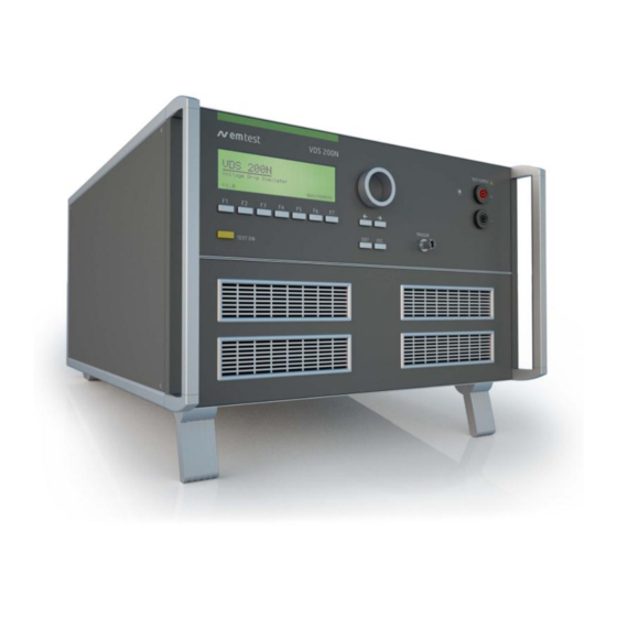
The VDS 200Nx is a low frequency amplifier. It simulates the
battery power supply of a vehicle and complex power supply
distortions in the power range up to 12'000W. A lot of different
waveforms are integrated as standard such as pulse 2b and
pulse 4 required in ISO 7637.
Version: 5.19 / 03.09.2013
Replaces: 5.18 / 17.06.2013
Filename: UserManual-VDS200Nx-E-V519.doc
Printdate: 03.09.13
N15,
N30
N50
N150
N200
N50.1
N100.5 N100.6
ISO 7637
SAE J1113
Manufacturer spec
GM, Ford, Chrysler,
BMW, VW, PSA,
Renault, Fiat ....
Advertisement
Table of Contents

Related Manuals for EM TEST VDS 200N50

Summary of Contents for EM TEST VDS 200N50
- Page 1 M a n u a l f o r O p e r a t i o n VDS 200 series Voltage Drop Simulator pulses 2b, 4 VDS 200N10, N15, VDS 200N100, N150 N200 VDS 200N30.1 N50.1 ...
- Page 2 Switzerland Phone : +41 61 717 91 91 Fax : +41 61 717 91 99 URL : http://www.emtest.com Copyright © 2013 EM TEST Switzerland GmbH All right reserved. Specifications subject to change Manual for Operation V 5.19 2 / 57...
-
Page 3: Table Of Contents
EM TEST VDS 200 Series Contents Model Overview ............................. 5 1.1. VDS Models ..............................5 1.2. RDS Models ..............................7 Operating Functions ............................. 8 2.1. Front view ..............................8 2.2. Rear view ..............................9 2.3. VDS200N100.1 operating elements ......................11 2.3.1. - Page 4 Calibration and Verification ......................... 47 6.5.1. Factory calibration ............................47 6.5.2. Guideline to determine the calibration period of EM Test instrumentation ..........47 6.5.3. Calibration of Accessories made by passive components only: ..............47 6.5.4. Periodically In-house verification ........................ 47 Delivery Groups ............................
-
Page 5: Model Overview
EM TEST VDS 200 Series Model Overview 1.1. VDS Models Standard models Model Name till 2008 Voltage voltage current Inrush Sinus f max VDS 200B0 = 0A – 10A ± 10% VDS 200N10 ( 15A 500ms ) 50kHz VDS 200B = 0A –... - Page 6 EM TEST VDS 200 Series Special models Special models have the index VDS200N200.x. The difference to standard models is the voltage and current ranges. The operation is the same as by the standard VDS equipment’s. The maximum overcurrent trips at the rated current.
-
Page 7: Rds Models
EM TEST VDS 200 Series Special Models not listed in this list are customized versions. These devices have a Firmware version x.xxaxxsxx. Some parameters can differ to the specs of this manual. The rest of the operation is according to this manual. -
Page 8: Operating Functions
EM TEST VDS 200 Series Operating Functions 2.1. Front view Display Function keys "F1..F7" BNC CRO Trigger ( for oscilloscope) "TEST ON" Earthplug for voltage probes Knob (Inc/Dec) 10 LED Power ON 11 DUT test supply output Cursor keys "" and ""... -
Page 9: Rear View
EM TEST VDS 200 Series 2.2. Rear view 1 EUT Test supply 5 Mains input 9 USB Interface 2 Reference earth connection 6 Fuses 10 CN connector not used 3 Analogue input 0 - 10V 7 Power On switch 11 Fail 1... - Page 10 EM TEST VDS 200 Series 1 EUT Test supply 5 Mains input 9 USB Interface 2 Reference earth connection 6 Fuses 10 CN connector not used 3 Analogue input 0 - 10V 7 Power On switch 11 Fail 1 4 External trigger...
-
Page 11: Vds200N100.1 Operating Elements
EM TEST VDS 200 Series 2.3. VDS200N100.1 operating elements 2.3.1. Front view VDS200N100.1 Display Function keys "F1..F7" BNC CRO Trigger ( for oscilloscope) "TEST ON" Earthplug for voltage probes Knob (Inc/Dec) 10 LED Power ON 11 DUT test supply output Cursor keys ""... -
Page 12: Rear View Vds200N100.1
EM TEST VDS 200 Series 2.3.2. Rear view VDS200N100.1 12 Main Switch 14 DUT Test supply output 13 Sense input 15 Mains input CEE 3x400V 16A 12 Power On switch The power on switch is a circuit breaker model Siemens 3RV10 21-1JA1 with overcurrent protection. For switch on the user has to put the switch in the illustrated position. -
Page 13: Vds 200N100.4 Operating Elements
EM TEST VDS 200 Series 2.4. VDS 200N100.4 operating elements The VDS 200N100.4 includes an internal overvoltage protection selectable by a switch at the rear side. The protection levels are 20V, 30V, 40V and 60V. The overvoltage protection works as a crowbar, switches in a few µs and discharges the storage capacitor bank and switches off the charging rectifier. -
Page 14: Vds 200N100.6 Operating Elements
EM TEST VDS 200 Series 2.5. VDS 200N100.6 operating elements General operating elements Autowave (optional control device) VDS200 front for manual operating Emergency button (turn for release) DUT supply ,sense front Rear panel (VDS and Autowave functions) DUT supply , sense rear side... -
Page 15: Safety With Voltage Setting
EM TEST VDS 200 Series 2.6. Safety with voltage setting To ensure a safe operation of the DUT (Device Under Test) some restrictions in the operation of the instrument are built in. These restrictions are explained within this paragraph. The VDS basically is divided into 2 different operation modes, which includes their individual test routines and supply voltage setting. -
Page 16: Operation
Any waveform can be generated up to the upper bandwidth of the unit. F7 Service Set-up, self-test, addresses of EM Test can be selected and displayed. Manual for Operation V 5.19... -
Page 17: Change Of Parameters
EM TEST VDS 200 Series 3.2.1. Change of parameters Easy and very fast operation of all standard functions of the equipment. The latest simulator settings are stored automatically and will be recalled when Quick Start is next selected. Page 5 (Show parameters) ISO Pulse 4 = 12.0V... -
Page 18: Wave Simulator
EM TEST VDS 200 Series 3.3. Wave Simulator Page 2 Waveform Simulator F1 : Standards F2 : Functions F3 : DC Power Supply Page 3 STANDARDS F1 : ISO 7637 F2 : ISO 16750-2 or WD 03/2000-2 F3 : JASO... -
Page 19: Iso 7637
EM TEST VDS 200 Series 3.3.1. ISO 7637 3.3.1.1. Pulse 4 voltage drop This pulse simulates supply voltage reduction caused by energizing the starter-motor circuits of internal combustion engines, excluding spikes associated with starting. tf [Vb-Va1] < 5ms Limits depends VDS voltage range Input restrictions 0.0 V <= Vb + Va1 <= 30.0V (60.0V) -
Page 20: Iso 16750-2 Wd 03/2000-2
EM TEST VDS 200 Series 3.3.2. ISO 16750-2 WD 03/2000-2 3.3.2.1. Short voltage drop This test is to simulate the effect of a classical fuse actuation in another circuit. tr, tf = 10ms Limits depends VDS voltage range Input restrictions ... -
Page 21: Supply Voltage Profile
EM TEST VDS 200 Series 3.3.2.3. Supply voltage profile This test is to determine the reset behavior of the device under Test at different voltage drops. This test is applicable to equipment with reset function. Parameters: 0.0V 30.0V (60.0V) - 30.0V (- 60.0V) 30.0V... -
Page 22: Sinus Sweep
EM TEST VDS 200 Series 3.3.2.5. Sinus Sweep This test simulates a residual a.c. on the dc supply During Int f3 is applicated Limitations Vb + Vp <= 30.0V (60.0V ) Vb - Vp = 0.0V For frequency setting see the following limitations... -
Page 23: Jaso Test 1
EM TEST VDS 200 Series 3.3.3. Jaso Test 1 Limitations = VB1 >= VB3 >= VB2 <= Fn >= 1 / F1 Parameters: 0.0V 30.0V (60.0V) 0.0V 30.0V (60.0V) 0.0V 30.0V (60.0V) 0.1s 99.99 s 0.1s 99.99 s 0.1Hz 99.9 Hz... -
Page 24: Functions
EM TEST VDS 200 Series 3.3.4. Functions 3.3.4.1. Sine wave Limitations Vn + Vp <= 30.0V (60.0V) Vn - Vp = 0.0V For frequency setting see the following limitations max 6Vpp up to the full 50kHz range max 16Vpp up to 25kHz Parameters: 0.0V... -
Page 25: Jump Start
EM TEST VDS 200 Series 3.3.4.2. Jump Start Limitations V1 + V1 <= 30.0V (60.0V) = 0.0V V1 + V1 Parameters: 0.0V 30.0V (60.0V) - 30.0V (- 60.0V) 30.0V (60.0V) 0.01s 999.99s 0.01s 999.99s 0.01s 999.99s 0.1s 99.9s 30,000 / endl. -
Page 26: Pulse 4 ( Gm 9105 P)
EM TEST VDS 200 Series 3.3.4.4. Pulse 4 ( GM 9105 P) In addition to the ISO pulse 4 a 5Hz ripple of 1Vp-p is superimposed during t9 to Va. tr, tf = 10ms Input restrictions Vb + Va1 30.0V 0.0 V... -
Page 27: Dc Source
EM TEST VDS 200 Series 3.3.4.5. DC source Page 3 (Show parameters) DC POWER SUPPLY Vb = 13.5 V I = 30.0A Stop Change The user can select the parameter to be changed with the related function key and change the value by turning the knob. -
Page 28: Service
F2 : Selftest F3 : Setup Addresses The addresses of the EM TEST AG and the EM TEST GmbH are shown. The addresses of all EM TEST Sales agencies are listed on the web site of EM Test under : www.emtest.com Selftest The operator can initialize a self test procedure to check the operation of the instrument. -
Page 29: Setup
EM TEST VDS 200 Series 3.5. Setup This menu helps the user to define the configuration of the VDS 200. SETUP F1 : Change language F2 : LCD Backlighting F3 : Interfaces F4 : Keyboard-Beeper F5 : Timer F6 : Set voltage F1 Change language The user can chose between two languages, German and English. -
Page 30: Test Equipment
EM TEST VDS 200 Series Test Equipment 4.1. Construction The Voltage Drop Simulator VDS 200 is built in a 19" housing and is divided into two parts, the control unit and the power electronics. The 100A type is designed in a small rack on wheels. -
Page 31: Arbitrary Wave Simulator
EM TEST VDS 200 Series 4.3. Arbitrary Wave Simulator The following diagram shows the principal layout of the amplifier. By controlling the semiconductor switches nearly any waveshape can be simulated. The amplifier is used generally as a high power dc supply for feeding the equipment under test. -
Page 32: Fuses
EM TEST VDS 200 Series 4.4. Fuses The mains fuses of the VDS 200 generators up to 100A DUT current are located at the rear side of the unit. Depends of the fuse model you can replace it manually or with a screw driver tool. -
Page 33: Overvoltage Protection
EM TEST VDS 200 Series 4.5. Overvoltage protection General With the overvoltage protection the user can protect the output voltage in case of an unwanted overvoltage at the VDS200 output in case of wrong voltage setting or failure. The overvoltage protection is a hardware crow bar that will cut down the voltage output of the VDS 200 and shut down the output voltage. -
Page 34: Function
EM TEST VDS 200 Series 4.5.2. Function The overvoltage protection consists of two parts: Crowbar switch with the hardware. A TVS diode will limit the max. overvoltage in the first µs till the security power switch will disconnect the DUT from the dc source. -
Page 35: Level Settings By The User
EM TEST VDS 200 Series 4.5.4. Level settings by the user The protection level factory setting is 60V. For change the protection level the user must proceed the following steps: The protection level setting must be done from people who are trained to work with electrical devices. -
Page 36: Typical Protection Behavior
EM TEST VDS 200 Series 4.5.5. Typical protection behavior The following pictures show the typical behavior of the crowbar protection in case of an overvoltage. Protection level 20V Protection level 30V Protection level 40V Protection level 60V Manual for Operation V 5.19... -
Page 37: Technical Data
EM TEST VDS 200 Series Technical Data 5.1. Test level Voltage for VDS 200NXB = 0V - 60V ± 10% with 0.1V steps setting internal ADC 8 Bit : approx. 0.24V at range 0…60V Output resolution = 0A – 10A ± 10%... -
Page 38: General
EM TEST VDS 200 Series 5.5. General Dimensions Device HU Unit Dimension H x W x D Weight VDS 200N10, 28 x 45 x 40 cm 49 kg VDS 200N15, 28 x 45 x 40 cm 49 kg VDS 200N30... -
Page 39: Test Routines
EM TEST VDS 200 Series 5.6. Test routines Arbitrary Wave Generator Standards ISO 7637 F1: Pulse 4 F2: Pulse 2b ISO 16750-2 WD 03/2000-2 F1: Short voltage drop F2: Slow decrease / increase F3: Supply voltage profile F4: Pulse ’Starting profile’... -
Page 40: Technical Data Vds 200N100.2
EM TEST VDS 200 Series 5.9. Technical data VDS 200N100.2 The VDS 200N100.2 has additional the following technical specifications: Output voltage = -5 V - 40 V ± 10 % Settings in 0.1V steps internal ADC 8 Bit : approx. 0.24V at range 0…60V Output resolution = 0A –... -
Page 41: Technical Data Vds 200N100.6
EM TEST VDS 200 Series 5.10. Technical data VDS 200N100.6 The VDS 200N100.6 is a bipolar DC source with the following technical data: Output voltage = -5 V to + 70 V ± 10 % Settings in 0.1V Steps internal ADC 8 Bit : approx. 0.24V at range 0…60V Output resolution = 0A –... -
Page 42: Dut Voltage Limitation On Dc Output
EM TEST VDS 200 Series 5.10.1. DUT voltage limitation on DC output The DB9 interface at the test supply output offers a limitation of the DC output voltage. The limitation is controlled by an external resistor connected to pin 7-8. -
Page 43: Voltage Attenuation At Sine Ripple Frequencies
EM TEST VDS 200 Series 5.10.2. Voltage attenuation at sine ripple frequencies Using an individual amplitude control with sine ripple, the user must compensate the attenuation of the amplifier frequency bandwidth. The table below shows the attenuator factor for frequencies range 1kHz to 100kHz. -
Page 44: Maintenance
EM TEST VDS 200 Series Maintenance 6.1. General The generator is absolutely maintenance-free by using a solid state semiconductor switch to generate the fast transients. 6.2. Test set-up When setting up the test national and international regulations regarding human safety have to be guaranteed. -
Page 45: Examples Test Setup
EM TEST VDS 200 Series 6.4. Examples Test setup Setup example with: AutoWave UCS 200N VDS 200Nx LD200N PFS 200N RDS 200N Note : Do never connect The PFS200N output 0-10V in parallel with any Autowave output. In this case the controlled DC source will deliver a wrong output signal. It is not allowed to connect two output sources in parallel. - Page 46 EM TEST VDS 200 Series Setup example with: AutoWave (former ARB2714) MPG 200 VDS 200Nx LD 200 EFT 200 CNA 200 Note : Do never connect The PFS200N output 0-10V in parallel with any Autowave output. In this case the controlled DC source will deliver a wrong output signal. It is not allowed to connect two output sources in parallel.
-
Page 47: Calibration And Verification
EM TEST equipment. EM TEST doesn’t know each customer’s Quality Assurance Policy nor do we know how often the equipment is used and what kind of tests are performed during the life cycle of a test equipment. Only the customer knows all the details and therefore the customer needs to specify the calibration interval for his test equipment. -
Page 48: Delivery Groups
EM TEST VDS 200 Series Delivery Groups 7.1. Basic equipment Simulator VDS 200... Power supply cable Set of safety laboratory cables Manual Identical accessory parts are delivered only once if several devices are orders. The delivered packing list is in each case valid for the delivery. -
Page 49: Appendix
EM TEST VDS 200 Series Appendix 8.1. Declaration of CE-Conformity Manufacturer : EM TEST Switzerland GmbH Address: Sternenhofstr. 15 CH 4153 Reinach Switzerland declares, that under is sole responsibility, the product’s listed below, including all their options, are conformity with the applicable CE directives listed below using the relevant section of the following EC standards and other normative documents. -
Page 50: Rds 200N
EM TEST VDS 200 Series 8.2. RDS 200N The RDS 200N in combination with the AutoWave as an arbitrary generator can be used to test according to Ford ES-XW7T, test procedure CI 230, simultaneously onto a max 4 channel DUT. The RDS 200N includes a sink and can therefore also be used to generate arbitrary waves as required in different standards. -
Page 51: Rearside Rds 200
EM TEST VDS 200 Series 8.2.2. Rearside RDS 200 1 Analogue input 0 - 10V 3 Connector 2 Test Supply output rearside 4 Power On switch with fuse Analogue input 0-10V The internal amplifier can be controlled by an external signal generator. -
Page 52: Technical Data Rds 200N
EM TEST VDS 200 Series 8.2.3. Technical data RDS 200N Output Voltage for RDS 200 = 0.0V - 16V ± 10% = 0.0A – 10A ± 10% Current Input/output Test supply + / - output Safety laboratory plugs at front and rear panel Analog control input 0.0 - 10V / 10k... -
Page 53: Vds 200N Blockdiagram
EM TEST VDS 200 Series 8.3. VDS 200N Blockdiagram Manual for Operation V 5.19 53 / 57... -
Page 54: Bipolar Vds 200N Potential Diagram
EM TEST VDS 200 Series 8.4. Bipolar VDS 200N Potential diagram VDS200N30.1 VDS200N50.1 VDS200N100.1 Manual for Operation V 5.19 54 / 57... -
Page 55: Connectors
EM TEST VDS 200 Series 8.5. Connectors For additional connectors please download the catalogue from Multi Contact : www.multi-contact.com 100A Plugs and connectors from Multi Contact Safety sockets KBT6AR-N/...-S with snap-in lock and crimp connection Model KBT6AR-N/...-S safety sockets are sockets with locking devices and for crimping onto highly flexible Cu conductor with cross-sections of 10mm2, 16mm2 or 25mm2. -
Page 56: Spare Parts Transistors
EM TEST VDS 200 Series 8.6. Spare parts transistors There are some VDS 200N models where EM Test delivers spare transistors. For replace any transistors in the power PCB EM Test delivers a couple of spare transistors with the unit. -
Page 57: Vds 200N Menu Overview
Start run the test procedure Stop stops the test procedure Change Select the parameters Continue the test procedure Service Addresses F1 Addresses Addresses of EM TEST and their F2 Self test representatives are displayed. F3 Set-up Selftest Selftest F1 Press the displayed Key...
Need help?
Do you have a question about the VDS 200N50 and is the answer not in the manual?
Questions and answers