Table of Contents
Advertisement
Advertisement
Table of Contents

Related Manuals for ExTox ET-8D


Summary of Contents for ExTox ET-8D
- Page 1 Instruction Manual ExTox Control Units Series ET-8 and ET-4D2...
- Page 2 Page 2 of 39...
- Page 3 ExTox Control Units Series ET-8D and ET-4D2 Foreword We thank you very much for your confidence in our products and us, the ExTox Gasmess- Systeme GmbH. The Control Units of the Series ET-8D and ET-4D2 as well as all other ExTox-Products and services stand for our high quality targets.
-
Page 4: Table Of Contents
Instruction Manual ExTox Control Units Series ET-8D and ET-4D2 Content Introduction Features of The Control Units Series ET-8D Series ET-4D2 Common Features of the Series ET-8D and ET-4D2 Indications and Facilities of the Control Units Series ET-8D Series ET-4D2 Configuration... - Page 5 Instruction Manual ExTox Control Units Series ET-8D and ET-4D2 Digital Data Output Data Formate Parameters of Serial Data Transfer Composition of recorded Data 6.3.1 Series ET-8D 6.3.2 Series ET-4D2 Interface Profibus DP or ModBus Application Measuring Function Use in combination with hazardous Areas...
-
Page 6: Introduction
We kindly ask you not to repair the control unit or to perform any changes which go beyond the measures described herein. Otherwise you endanger your own safety and your warranty claims of merchantability. In such cases please contact ExTox or authorised ExTox Service Partner. Third parties take the responsibility for correct performance of work if maintenance and repairs are done by them. -
Page 7: Features Of The Control Units
Control Units of the Series ET-8D and ET-4D2 after measuring them safely with our Ex- Tox transmitters. The Control Units could be combined with all ExTox-Transmitters ExSens (-I) and Sens (-I). The control units are available in wall mounted housing, for DIN-Rail installation and for installation in 19''-Rack or Control Panel. -
Page 8: Series Et-4D2
Instruction Manual ExTox Control Units Series ET-8D and ET-4D2 Series ET-4D2 4 input channels for transmitter (4-20 mA, three-wire system) or smoke detector 12 relay outputs, potential free, freely configurable 4 analogue outputs, potential free (only Type ET-4DA2 Measuring function for explosion protection: in conformity with Directive 94/9/EC (ATEX) -
Page 9: Indications And Facilities Of The Control Units
Instruction Manual ExTox Control Units Series ET-8D and ET-4D2 Indications and Facilities of the Control Units Series ET-8D ET-8D Gasmess-Systeme GmbH Status of Chan- nels 1 to 8: Störung Fault Operation Display (green) Alarm 3 Alarm 1, 2, 3 (red) -
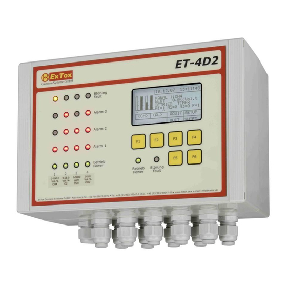
Page 10: Series Et-4D2
Instruction Manual ExTox Control Units Series ET-8D and ET-4D2 For that purpose the bar graph and detail indication setting has to be activated in the dis- play. Then you have to select the corresponding channel and afterwards the Alarm A1, A2, A3 via the functional keys F3 (<AL) or F4 (AL>). - Page 11 Instruction Manual ExTox Control Units Series ET-8D and ET-4D2 sub-menu or to safe the set parameters. Any deviation from these rules being generally valid will be separately indicated in the following descriptions If the alarm is configured as latching, it has to be reset manually in case the alarm condition is no longer present.
-
Page 12: Configuration
Attention: On Access Level 3 very important basic settings for the safe function of the gas detection device could be changed. This level should only be accessible for especially trained staff. Therefore this level is reserved for the ExTox-Service. Level... -
Page 13: Channel Configuration
Instruction Manual ExTox Control Units Series ET-8D and ET-4D2 Channel Configuration Access Level to perform changes of the parameter settings: 2 Attention: For transmitters based on the measuring principle catalytic combustion and semi- conductor the sensor signal might fall again into the measuring range due to the suppres- sion of oxygen at very high concentrations of flammable gases. - Page 14 A latching channel fault has always to be reset manually (see 5.3). You can also connect ExTox smoke detectors to the ET-8D and ET-4D2 (see 10). In this case different procedures have to be considered. Page 14 of 39...
-
Page 15: Relay Configuration
Instruction Manual ExTox Control Units Series ET-8D and ET-4D2 Series ET-8D: The smoke detector function is activated with parameter "RM" in the gas list. Please select "100" as measuring range. The alarm levels have to be adjusted to "10", "11"... -
Page 16: Calibration
Instruction Manual ExTox Control Units Series ET-8D and ET-4D2 Menu Text Selection Function Matrix set- Indicates whether the alarm or the channel fault is con- tings Channel sidered when evaluating the triggering condition (1) or not (0). A1 A2 A3 F Example: Channel 1, 2. -
Page 17: Time/Date
The safety functions are not affected but the batteries should be ex- changed on the next maintenance done by ExTox. 0 to 59 Minutes of Control Unit time, changes via F2/F3 (+/-) -
Page 18: Series Et-4D2
Instruction Manual ExTox Control Units Series ET-8D and ET-4D2 4.5.2 Series ET-4D2 Menu Text Selection Function Selection via F1 (20mA): Analogue Inputs 4..20 mA CH1 to CH4 0.00 to The actual value of the transmitter output current which is 25.00 mA pending at the entry of the control unit prior to processing is displayed. -
Page 19: Password
0.5 it is only 50 % of the original measuring range. When selecting the alarm levels please ensure that they can still be triggered safely. For complete use of the adjustment range ExTox therefore recommends to avoid alarm levels > 50 % of the measuring range. Description of the Adjustment Process The formula mentioned above to convert the measuring value changes when using this form of adjustment. -
Page 20: System Parameters
Instruction Manual ExTox Control Units Series ET-8D and ET-4D2 System Parameters This menu consists of eight submenus. The software version is additionally displayed on top on the right side. 4.8.1 Maintenance Access level to activate the service mode: 1 The activation of maintenance functions in this menu is indicated by means of the blinking operation LED and the relay K26 and K14 (Maintenance) is not engaged. -
Page 21: Inputs 4
Instruction Manual ExTox Control Units Series ET-8D and ET-4D2 4.8.2 Inputs 4…20 mA Access Level to perform changes of the parameter settings: 3 Menu Text Selection Function Hysteresis 0 % to 20 % Fixes the alarm hysteresis in percent of the end value of measuring range. -
Page 22: Memory Test
Instruction Manual ExTox Control Units Series ET-8D and ET-4D2 Menu Text Selection Function 20mA-H(old) OFF, This function enables the suppression of alarm triggering by means of external peripheral devices, for example SPS, in case the gas detection system is in service mode. -
Page 23: Series Et-4D2
IMC, BIO usw. described in this Instruction Manual. The other settings are only activated in case the control units are used in ExTox Integral Measuring Concepts IMC. The additional function supplements and deviations are described in the IMC Instruction Manual. -
Page 24: Options
Measured values and status messages are put out cyclically in intervals of 10 s. All remaining settings are only activated in case the control units are used in ExTox Integral Measuring Concepts IMC. Corresponding functional amendments and differences are de- scribed in a separate IMC-Instruction Manual. -
Page 25: Operation Of The Control Unit
Instruction Manual ExTox Control Units Series ET-8D and ET-4D2 Operation of the Control Unit The features which especially mark the measuring modes are emphasised by heavy print in the following chapters. Measuring Mode There are no faults and alarms. The measured value is within the range between 0 % and 100% of the end value of measuring range. -
Page 26: Alarms
Instruction Manual ExTox Control Units Series ET-8D and ET-4D2 Relays ET-8D (for ET-4D2 in brackets) K1 to K24 (K12): not triggered Fault Control Unit K25 (K13): closed Maintenance K26 (K14): closed Alarms Minimum one configured alarm on one channel level is triggered. -
Page 27: Channel Fault
When using ExTox- Transmitters safe measurement is ensured when configuring the channel fault as latching (see 4.1). -
Page 28: Fault Of Control Unit
The display indicates patterns during that time. After that the company name and the Inter- net Address of ExTox are indicated on the start screen for 120 seconds. The remaining time until starting normal operation a countdown running downwards is displayed. -
Page 29: Analogue Outputs 4
The digital inputs E1 to E3 are normally without function, but they can be used for customer specific requirements. On demand please do not hesitate to contact ExTox. 5.11 Smoke Detectors Please pay attention to the differences between the two control unit types ET-8D and ET- 4D2. -
Page 30: Digital Data Output
Type Test for measuring technical function. Use of this data is for information and storing purposes, but not for safety functions. It is possible to record the data by means of an ExTox Data Logger ET-SL which is available as accessory (see Chapter 10). -
Page 31: Composition Of Recorded Data
Instruction Manual ExTox Control Units Series ET-8D and ET-4D2 Composition of recorded Data This description is based on the data evaluation via Microsoft EXCEL . 6.3.1 Series ET-8D Column Content Format Example Explanation Date ASCII 08.01.2005 TT.MM.JJJJ Time ASCII 12:23:00... - Page 32 Instruction Manual ExTox Control Units Series ET-8D and ET-4D2 Column Content Format Example Explanation Channel 3 FAULT ASCII 1 = fault; This stands for transmitter Channel 4 FAULT ASCII faults, such as for example Channel 5 FAULT ASCII defects of the transmitter...
-
Page 33: Series Et-4D2
The configuration of the control unit for operation with interface module is done factory- sides before delivery and is marked on the test certificate (in case an existing system should be converted please do not hesitate to contact the ExTox-Service.). Please pay attention to the remarks in the corresponding amendment to this Instruction Manual. -
Page 34: Application
The use of Gas Detection Systems for explosion and health protection requires special care. Besides qualified support of ExTox and the detailed information in the Instruction Manuals as well as Technical Data Sheets ( DB) there are several guides to assist you for the safe use and operation of Gas Detection Systems. -
Page 35: Installation
In case the standard length ( DB) does not fit, please do not hesitate to contact ExTox. As an option the different types can also be supplied in combined "Sandwich"- design. In this case the clamps are freely accessible on the backside of the housing. -
Page 36: Smoke Detectors
Instruction Manual ExTox Control Units Series ET-8D and ET-4D2 this case the connection between the pins SHLD and PE has to be set at the Jumper J 4001 (between Relay K9 and input channel CH1). Please bear in mind that the cable glands have to be firmly tightened to ensure the suffi- cient strain-relief. - Page 37 Instruction Manual ExTox Control Units Series ET-8D and ET-4D2 ET-4D2 (up to December 2013) Rauchmelder DP721R (1 bis n-1) Rauchmelder DP721R (n) ET-4D2 Smoke detector DP721R (1 to n-1) Smoke detector DP721R (n) R = 5k6 R = 5k6 ET-4D2 since software REV131209R (January 2014) Rauchmelder DP721R (1 bis n-1) vorkonfektionierte Widerstände entfernen...
-
Page 38: Maintenance Of Gas Detection Systems
You as user of the gas detection system bear the responsibility for the correct performance of the maintenance. ExTox as manufacturer can only place all necessary details to build up your specific maintenance concept at your disposal. We are glad to support you with this task and to submit a maintenance quotation acc. -
Page 39: System Check
Make sure that measures have been taken to avoid unintended triggering and transmission of alarms before applying test gas. Activate the alarm bypass in service mode at your ExTox Control Unit, deactivate automatically triggering protection measures or inform the respon- sible maintenance personnel.
Need help?
Do you have a question about the ET-8D and is the answer not in the manual?
Questions and answers