Table of Contents
Advertisement
Advertisement
Table of Contents

Related Manuals for ExTox ET-4D2 Series


Summarization of Contents
2 Features of The Control Units
2.1 Series ET-8D
Features of the ET-8D control unit, including inputs and outputs.
2.2 Series ET-4D2
Features of the ET-4D2 control unit, including inputs and outputs.
2.3 Common Features of the Series ET-8D and ET-4D2
Lists common features shared by both ET-8D and ET-4D2 control units.
3 Indications and Facilities of the Control Units
3.1 Series ET-8D
Describes the display, LEDs, and functional keys for the ET-8D unit.
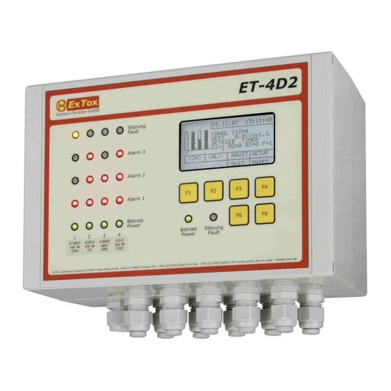
3.2 Series ET-4D2
Describes the display, LEDs, and functional keys for the ET-4D2 unit.
4 Configuration
4.1 Channel Configuration
Defines parameters for configuring individual measurement channels.
4.2 Relay Configuration
Configures relay behavior based on alarms, faults, and logic.
4.3 Calibration
Describes the process for calibrating the control unit.
4.4 Time/Date
Describes how to set the system's time and date.
4.5.1 Series ET-8D
Details analogue input parameters and voltage checks for ET-8D.
4.5.2 Series ET-4D2
Details analogue input parameters and voltage checks for ET-4D2.
4.6 Adjustment
Describes how to adjust transmitters via the control unit.
4.7 Password
Explains password protection for access levels.
4.8.1 Maintenance
Activates and describes service/maintenance mode features.
4.8.2 Inputs 4...20 mA
Configures parameters for 4-20 mA input signals.
4.8.3.1 Series ET-8D
Shows memory test results for RAM, ROM, and EEPROM on ET-8D.
4.8.3.2 Series ET-4D2
Shows memory test results for RAM, ROM, and EEPROM on ET-4D2.
4.8.4 Language
Selects the language for menus and display.
4.8.5 Mode
Sets the operational mode of the control unit.
4.8.6 Options
Configures serial interfaces and other options.
4.8.7 AQUIT
Configures whether alarm reset requires password.
4.8.8 Alarm
Displays recent alarm and fault status changes.
5 Operation of the Control Unit
5.1 Measuring Mode
Describes the normal operational state with no faults or alarms.
5.2 Deactivation of Channel
Explains how to temporarily disable a channel from monitoring.
5.3 Alarms
Details how to reset triggered alarms.
5.4 Under-Scale and Over-Scale of Measuring Range
Explains conditions outside the measuring range.
5.5 Channel Fault
Describes how to reset channel faults.
5.6 Fault of Control Unit
Explains faults related to the control unit's internal monitoring.
5.7 Programme Run Monitoring (Watchdog)
Describes the watchdog function for program monitoring.
5.8 Initialisation (Start-up of System)
Explains the initialisation process after power connection.
5.9 Analogue Outputs 4...20 mA (only Types ET-8DA and ET-4DA2)
Describes the 4-20 mA analogue output behavior.
5.10 Digital Inputs
Explains the functionality of digital inputs.
5.11 Smoke Detectors
Details the use and configuration of smoke detectors.
5.11.1 Series ET-8D
Details connecting smoke detectors to the ET-8D unit.
5.11.2 Series ET-4D2
Details connecting smoke detectors to the ET-4D2 unit.
5.12 RS 485-Interfaces for Transmitter ExSens-I and Sens-I
Describes RS485 interface for specific transmitters.
6 Digital Data Output
6.1 Data Formate
Describes the ASCII format for data output.
6.2 Parameters of Serial Data Transfer
Specifies parameters for serial data transfer.
6.3 Composition of recorded Data
Details the structure and content of recorded data.
6.3.1 Series ET-8D
Details the data composition for the ET-8D series.
6.3.2 Series ET-4D2
Details the data composition for the ET-4D2 series.
6.4 Interface Profibus DP® or ModBus®
Configuration for Profibus DP and Modbus interfaces.
7 Application
7.1 Measuring Function
Explains the system's primary measuring function.
7.2 Use in combination with hazardous Areas
Guidelines for using the system in hazardous locations.
8 Installation
8.1 Mechanical Installation
Covers physical mounting and placement of the unit.
8.2 Electrical Installation
Details electrical connections and safety requirements.
8.3 Smoke Detectors
Details the installation of smoke detectors.
8.3.1 Series ET-8D
Wiring scheme for connecting smoke detectors to ET-8D.
8.3.2 Series ET-4D2
Wiring scheme for connecting smoke detectors to ET-4D2.
9 Maintenance of Gas Detection Systems
9.1 Basic Information
Provides general information on maintenance procedures.
9.2 Visual Check
Outlines visual inspection steps for the system.
9.3 Functional Check
Describes calibration and functional testing of the system.
9.4 System Check
Checks switching functions and system parameters.
Need help?
Do you have a question about the ET-4D2 Series and is the answer not in the manual?
Questions and answers